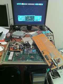
I’ve added yet another room cluttering object to the office; an Atari 520STFM. The ST was always ‘the other one’ in the 16 bit era that the Amiga tended to dominate. Both the ST and the Amiga had a similar speed 68000 CPU, similar amounts of RAM, but big differences when it came to the extra hardware chipset stuff. The ST tended to be painted as the worser cousin, but I always had a soft spot for the underdog … and per all my other computers ‘was really quite curious as to how you interact and use it’. It has to be one of the few OS’s that boot’s from ROM to a graphical desktop.
So up until a few days ago I had never used an Atari ST, so everything is ‘new’. It came with a mouse described as ‘dodgy’ and nothing else. It seems to be a UK ST. First challenge was to plug it in to a monitor. I ended up running two jumper wires into the odd 13 pin audio/video DIN socket on the back to get composite. That got me the classic ‘little green desktop’. Then I noticed how bad the mouse was. I could move the mouse left and right, but up/down wasn’t really working. Some of the pins in the DB9 sockets had been pushed in a bit, which I fixed when I later pulled it apart, but still the mouse would not go up and down. For now I’ve ended up using my PIC16F based PS2 mouse to Amiga adapter, as supposedly an Amiga mouse and ST mouse are very similar. I just swapped pins 1 and 4 on the DB9 and it works.
That got me a mouse, so I tried formatting a disk. That did not work at all. I gave up for the moment, as I wanted to try the gotek drive in it. I’d bought the gotek ages ago, and put the cortex firmware on it to use with Amigas … but I’ve honestly ended up using real floppies more on the Amiga. For the ST however, I thought it might be easier to use the gotek. The HxC firmware can now work on a Gotek and most importantly it can pretend to be an ST drive. The HxC firmware costs 10 euros though, but is money well spent.
So now I could boot something. I first tried Star Raiders and all was good.
 So the other thing I did was to route the composite video out to the RCA connector used by the RF modulator. That way I could at least get composite out without needing some delicate wires. I followed a post here (look for a post by CodeKiller) where you remove two resistors inside the modulator and run a wire through. I ended up running a wire from just behind the 13 pin DIN socket through to the modulator centre pin. So now I had a convenient way to get ‘some’ screen output. Composite output was OK. I debated whether to do some surgery to get svideo out, but then opted to try to get RGB working. Again the RGB signals come out the 13 pin DIN socket that is difficult to get a plug for. Initially I experimented with using pin header type connectors. 3 lots of 4 pin headers plus a separate wire into the 13 pin for ground. It was fiddly. I got some output, but had a lot of screen interference.
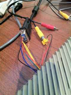
So then I just soldered some wires underneath the board to the pins of the 13 pin DIN and directly wired in a VGA socket. With that plugged in to the VGA of my Dell 2001FP (which does 15kHz/50Hz modes via VGA) I had a quite decent RGB picture.
Audio out (in this case mono) comes out of the 13 pin DIN as well. I just soldered in some wires running out the back to an RCA socket. And then plugged that in to some speakers. The audio was a puzzle for me for a while. Everytime I plugged in the jack for my speakers the ST would produce a lot of noticeable screen interference. Unplug it, and all was nice and crisp again. This led to a lot of questions to my more knowledgeable brother who suggested it might be something to do with the speakers having a different power supply to the ST with both having their own switchmode PSU’s running at different frequencies and something about the ‘GND’ not quite being the same between the two. This led to some attempt to introduce a low pass filter (simple resistor/capacitor to filter to 10kHz) inside the speakers amp for the connection to the ST. The idea was to filter out high frequency crap coming from the speakers that may be making it to the ST. The low pass filter made a bit of a difference, but still left some ‘sparkle’ like interference.
Then I tried something relatively obvious; I changed the power supply for the speakers. They are just cheap USB powered speakers, so I was using an Apple USB charger to power them. I just swapped it for some other generic one in the cupboard (I think one that came with an LG phone) and tried again. Success. No more interference! (well there is still a tiny bit). I haven’t tried to remove the low pass filter in my speakers though.
So I’ve tried a few games. It’s interesting to see the differences for a game that I’ve seen on the Amiga compared to the ST. Often the graphics are similar. I think the ST lacks some of the colour depth of the Amiga, and technically doesn’t really have much hardware assistance, so sprites and scrolling are all done in software for the most part I think. But the graphics are generally pretty good. The sound is really where the differences are very noticeable. The Amiga has 4 channel 8 bit sampled sound. The ST has 3 voice ADSR style polyphonic I think. It’s not awful, but I think it was later in the ST era where they worked out how to get the most out of the sound hardware. Playability wise the games are pretty good.
So I’m mainly using the Gotek with a USB stick to load stuff, but I have also had another look at the original internal drive of the ST, and it just needed some IPA on it’s heads to bring it back to life. That then begged the question ‘how do you write floppies for use in an ST?’. Generally, because the ST floppy format is close to a normal PC format, you can actually just format disks in a PC … though I think modern versions of Windows struggle to format a double density 720K floppy (though I think you can do it from a command prompt). I ended up using linux disk commands on the atari wiki. That seemed to work reasonably well for 80 track .st images, but so far I haven’t been successful with 82 or 83 track images. I might try a different PC drive to see if that helps. I wish there was something similar to transwarp on the Amiga where you can pretty much ‘cat’ a disk image down a serial line from linux, then have it directly write the disk image using the floppy drive on the Amiga.
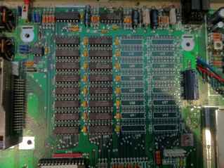
One of the first things I discovered as a new owner of a 520ST is that you probably wanted a 1040ST instead ;-). Quite a few games require at least 1MB of RAM. My 520STFM is a Rev D1 board that has space for 32 x 41256 DRAM chips of which only 16 are installed (coming from an Amiga background, the ST world seems to have had a zillion board revisions, so there are heaps of variations of what DRAM chips and location are used in the ST)
 So if I had another sixteen 41256’s I could easily upgrade it. I didn’t have that many 41256’s. The other popular choice is to wire in some old 30 pin SIMMs. You can use two 256KB ones to get an extra 512K … or you can actually add another 2MB by using two 1MB SIMMS (or upgrade all the way to 4MB by disabling the base 512KB).
I didn’t have any 1MB SIMMs, but I had some 256KB 30 pin SIMMs so I thought I would try those first. There are a few ‘instructions’ for doing this floating around the net including here and this RAMUPGRA.TXT .
So a few of these SIMM based upgrades suggest mounting your SIMMs on a vero or other type of protoboard and then running wires to the appropriate points. On my D1 board I wasn’t sure how I would do that without making the wires long, and I have negative childhood memories of trying to get DRAMs to run reliably on vero boards 😉 so I thought I would take the approach of putting each SIMM on its side essentially where each set of eight 41256’s would go and in turn keeping the wires to the ST motherboard as short as possible.
The first thing you need to do on a 520STFM is add the missing 68 ohm resistors (on my board R71, R72, R73). These are for the RAS and CAS lines to the new memory bank. Then I added on some 220nF caps in the spaces next to the empty 41256’s. I didn’t have 16, so I’ve only put in about 10 of them. Then I prepped each SIMM, by soldering short wires (about an inch in length) directly to them.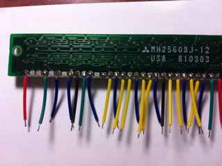
With the two wired up I soldering them directly to the pads where the 41256’s go. It’s a bit fiddly because I made the wires so short.
Here’s both soldered in and sort of standing up at a 45 degree angle.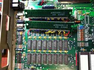
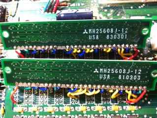
So the next key thing is to check that the power supply unit can go on top. The PSU sits on a metal plate maybe an inch above the motherboard exactly over the top of where the DRAMs go (on my D1 board). The idea is that the SIMMs are then pushed over so that the chips lean against the extra capacitors I put in (I used the little sausage like ones that are already in use for the existing 41256’s). The key problem then is that the non-chip side of the SIMMs is directly against the metal plate of the PSU which would obviously cause a short. So I now have a clear plastic sheet as insulator under the PSU for now.
So after all this soldering, I double checked and triple checked I hadn’t done anything stupid and powered on. It booted up. The ST TOS doesn’t bother to tell you how much memory you have, so I ended up finding two programs on a few sites; SYSINFO.PRG and MEMTEST.TOS. For me (the ST newbie) I then had to figure out to get these into an ST image that I could load onto a USB stick for my HxC Gotek. Eventually I had MSA converter up in a Windows VM to edit some .ST image that I thought wont likely boot (I used STOS Examples) … and now booting with that off the Gotek just dropped me into GEM and I could finally run SYSINFO to see that I did indeed have 1024K of memory. Of course this is all pointless if your DRAM is dodgy, so I ran MEMTEST.TOS a few times and confirmed that I was not getting any errors.
So now we can finally run Lemmings 2 on the ST!
Addendum: So that dodgy mouse that the ST came with. So it went left/right but not up/down properly. Strangely it seemed to go down only when I first got it, but then after pulling it apart, cleaning it and putting it back together it seemed to only go up. Eventually I hooked my logic analyser up to it to see what was going on. So the basic deal with these old mice is that for the x axis there are two wires generating pulses; Xa and Xb, and similarly for the y axis you have Ya and Yb. On an Atari mouse, pin 2 and 1 are Xa and Xb respectively and pin 3 and 4 are the Ya and Yb. With the mouse apart and the logic analyser hooked up to Xa and Xb, spinning the little optical wheel on the X axis showed lots of pulses on both Xa and Xb, but for Ya and Yb, the same test (but now with the y axis optical wheel) showed pulses on only pin 3 I think. So I pulled out the whole black base thing inside the mouse (the plastic assembly that the optical wheels sit in. That revealed the bare infrared LEDs and sensors. Now, I just moved a piece of cardboard between each of the 4 sensor pairs. This time I saw pulses on both the Ya and Yb. So I tried to clean things out a bit and put it back together thinking its possibly some minor alignment error of how the black base is screwed in. With it back together I had pulses on Ya and Yb … and a fully working mouse.