So I was given this Spectravideo SV-318 quite some time ago (thanks Bryce). It’s quite a cool looking computer. The red joystick knob on the right is an interesting feature.
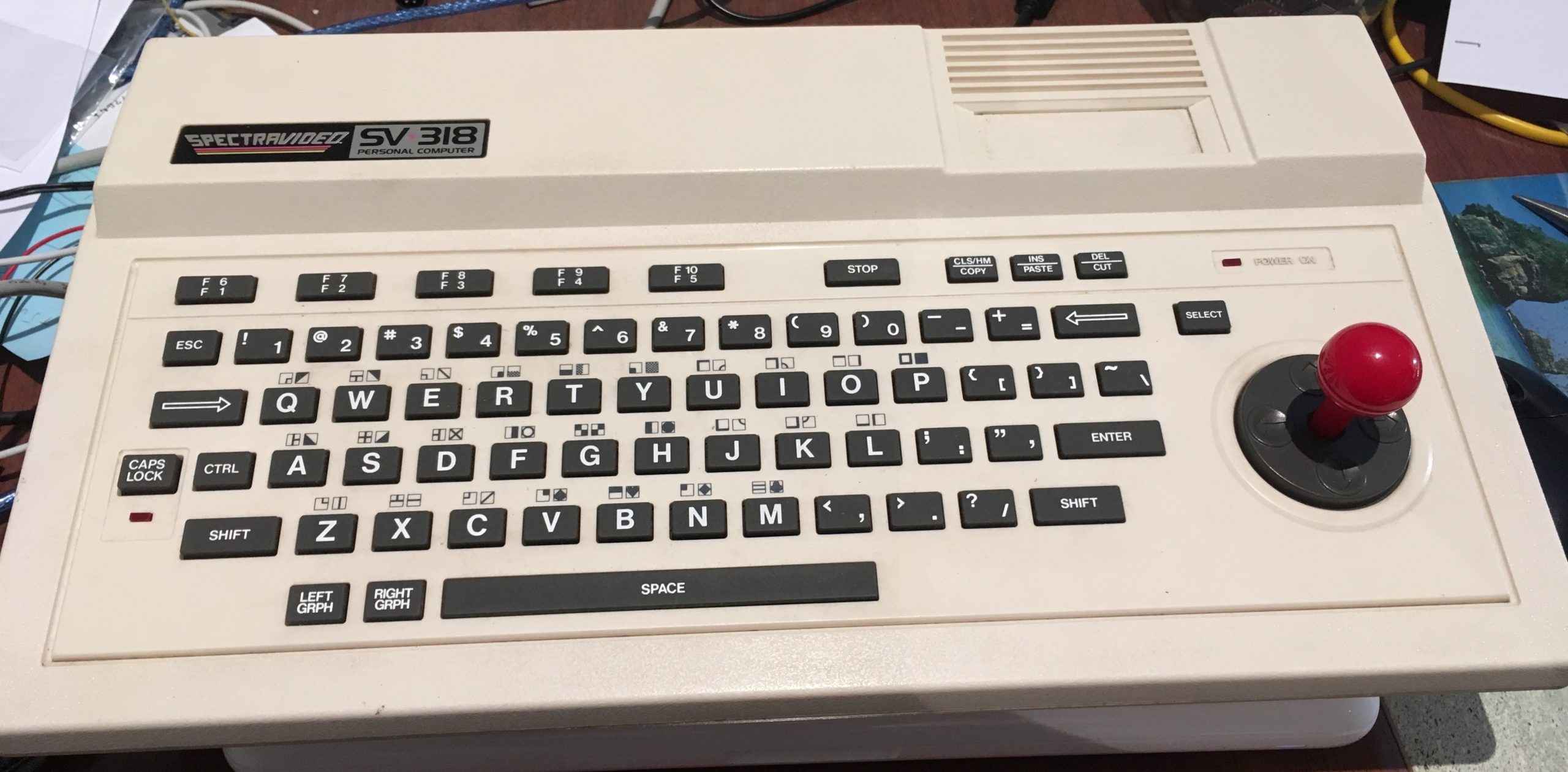 Alas, the built-in joystick is not very good, and I usually plug a real joystick in. The keyboard is a sort of mushy rubbery thing. You have to push and roll your finger a bit to type letters … but this is from 1983 and I can forgive a poor keyboard from that era. I have pulled the keyboard apart and tried to clean it … which helps a bit (and I am rather thankful it is a keyboard that actually can be disassembled)
Various references suggest that the SV-318 and later SV-328 machines were the basis for the MSX standard that came later in 1983. So you have effectively the same chips as MSX; Z80A CPU at 3.579MHz with (in this case) 16KB of RAM attached, 9918/9929 Video chip with dedicated 16KB of RAM, 8255 peripheral chip, AY-3-8910 sound chip and there is even a Microsoft BASIC in there too. It has bank switched memory so you can expand it beyond 64KB. All these things sound very similar to MSX, however it’s not compatible. I think all the IO chips are at different addresses to MSX, and the biggest difference (to me) is that the bank switched memory is quite different. MSX has a system where the four 16KB blocks in the 64KB address space can be swapped in and out. The Spectravideo just has two 32KB blocks.
I haven’t used the SV-318 much mainly because it did not come with it’s original power supply. And it’s an ‘odd’ power supply in that it produces two AC voltages (9VAC and 16VAC I think). The only thing ‘close’ to that that I have is the internal power supply of an original Commodore 1541 Disk drive (yes, the really big long ones). So it was awkward to set up and I only got as far as hacking together a small cassette interface board so I could ‘play’ converted .CAS files from a linux machine and load cassette images. I used this on the cassette port.
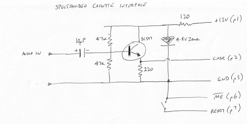
The little switch effectively is like the ‘play’ button. Usually I just leave it permanently closed, otherwise when you do a CLOAD it will ask you to press PLAY.
After I got things loading the SV-318 sat for about a year doing nothing.
So recently I’ve been Emulating ROMs and floppy drives in MSX using an Omega MSX2 computer. I actually wanted to do the WD279x floppy controller emulation for the Spectravideo …. but I’d just got the Omega going a few months ago so it ended up being my focus …. and hey the Spectravideo had that awkward power supply. I thought if I was going to do floppy disk emulation for the Spectravideo I would need to fix the awkward power supply setup.
This may seem cruel, but I decided to do a lot of surgery. The first idea was to use a bunch of DC-DC switchmode devices to generate the +5V, +12V and -5V internally from a 12VDC plug pack. But I decided to simply get rid of all the 4116 DRAM chips. They are the main reason it needs +5V, +12V and -5V (NB: The TBA520 colour chip also needs +12). I slowly desoldered all sixteen 4116’s and replaced them with sockets with 4164’s in them and cut a few traces here and there and removed the 7805 and 7812 linear regulators . I then hooked up an adjustable DC-DC switch mode PSU. 12VDC in and outputting a steady +5V. I just took the 12VDC output of the plug pack to drive the TBA520 colour chip.
That’s quite a bit of surgery and it didn’t work first go. The astute reader will note that I am wasting a lot of memory as the 4164’s have four times the capacity of the 4116s. But 4164’s are somewhat easier to find (though getting less so as the years pass) , and they obviously don’t need all the different power supplies that the 4116’s need. You just need to tie A7 high or low and adjust some power lines and they work just like a 4116. Months ago I had bought fifty 4164’s from some seller on ebay. The price seemed good so how could I refuse. Of course when they turned up I had no direct need for them so they sat in a box until now. I populated the 16 sockets with these new 4164s and after some troubleshooting worked out that none of them worked! So I had to find replacements.
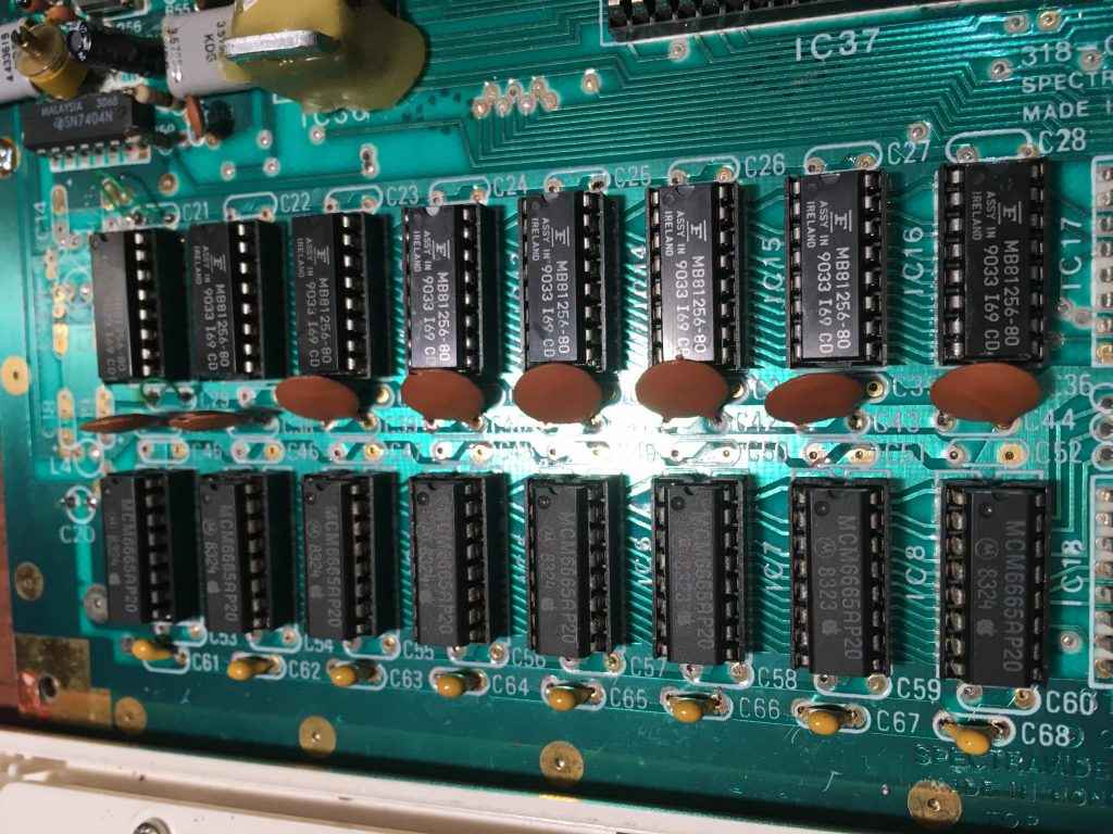
The even more astute reader will notice that the top set of 8 chips are actually 41256s. Because the fifty 4164s were DOA that meant scrounging for parts, and I found some 41256s that were desoldered from an old Amiga A501 expansion. The lower 8 chips are MCM6665AP20’s stolen from an Apple IIe. These lower 8 are the CPU ram chips. Initially I wired these up so that they appeared as 16KB of RAM just like the SV-318 with 4116’s. But later I made modifications to effectively expand the SV-318 to be a SV-328 (ie. 64KB of CPU RAM).
You can find the SV-318/SV-328 schematics on the Samdal Spectravideo Documents page or by poking around archive.org . The schematic mentions 4116’s or 4164’s but doesn’t show the logic that would allow the whole 64K of CPU ram to actually work (the 2nd set of schematics include some glue logic chip that was used in the SV-328 I think). Anyway, I couldn’t find anything online, so just guessed how to do the upgrade from 16K to 64K.
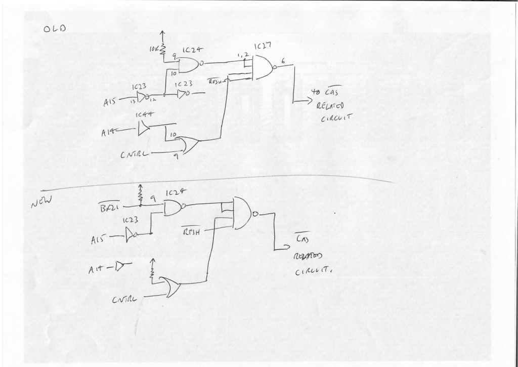 So the circuit above is what’s on page 2 of the schematics. The ‘old’ is for reference. Effectively when A15 and A14 are high, all inputs of the quad input NAND are high, so you get _CAS generated on the DRAMs effectively enabling them. ie. The built in 16K is only from 0xC000 – 0xFFFF. The ‘new’ section shows the main changes. We get _BK21 into the selection logic and remove A14 from the logic. So A15 high will give you 32K of RAM from 0x8000 – 0xFFFF . _BK21 low effectively enables the other 32K of RAM (when banked) at 0x0000 – 0x7FFF.
The photo below shows the 74LS32 (IC47) where A14 used to go (if you look closely at the ‘C” in IC47 you can see where I cut a trace), and I’ve attached a 4.7K pullup. You can also see I desoldered the 74LS20 (IC27). There is a trace that comes from pin 9 of IC24 (where I want _BK21 to go) , and it ends up as a via under the 74LS20. I could not work out where it went when it came to the top side of the board, so I went to the trouble of desoldering the 74LS20 (and putting it back) to prove that it actually does not go anywhere. This is really handy as it means you just need to connect a short wire from that via (for the pin 9 of IC24) to pin 9 of the 74LS20 ( _BK21 … which is on page 3 of the schematics in the bottom left). I just put this short wire underneath the board.
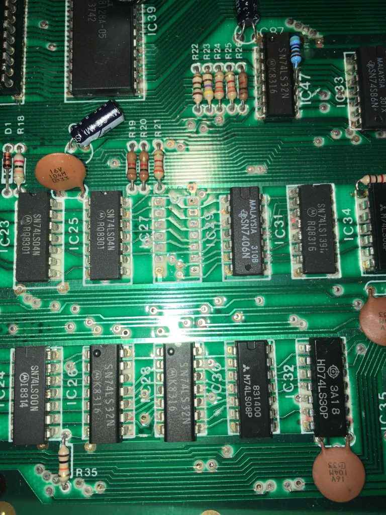
The other obvious change is to take the 4Y output of IC17 (74LS157) and connect it to all the A7 pins of the lower 4164s. A7 is pin 9 of the 4164s. A 4116 actually has +5V on pin 9, so you need to cut the trace that connects all pin 9’s so its disconnected from the +5V plane. The earlier photo also highlights that you need to remove a lot of the decoupling capacitors that were used for the extra voltage supply lines. And you’ll need to cut traces around these extra voltage lines to make sure they are isolated . On a 4164, pin 8 is +5V, and pin 16 is still GND. You’ll need to figure a nice way to connect pin 8 to +5V as its normally +12V on a 4116.
The other thing to note is that ‘Because Z80’ you need 4164’s with 128 cycle refresh (that’s why I used the old MCM6665 chips) since the Z80 is doing all the DRAM refreshing. You just need these for the lower set of 8 DRAMs.
So eventually I got that all going and instead of 12KB free in BASIC you now see 29KB free!! . I guess BASIC only sees the top 32K of RAM easily and you need to use some bank switching to use the 2nd 32K. I think the BASIC actually includes commands for bank switching as well.
One thing I found when I originally hooked up a power supply and cassette interface to the SV-318 is that there are very few programs you can load on it. The 16KB of CPU RAM Is a serious limitation. There are a lot more programs available for the SV-328 (or is it SVI-328?) as it has 64KB of CPU RAM. So now that I actually had the extra RAM I could actually load a lot more stuff. If you poke around archive.org and some other sites you’ll find various cassette dumps of games. These are all .CAS files. I worked out I could use the ‘castool’ program in the mame-tools package (at least on Fedora) to convert them to .WAV files:
castool convert svi armour.cas armour.wav
And then play the wav file with mplayer or similar. Some of the best games are the Coleco conversions (which never worked at all with only 16KB of CPU RAM). For the Coleco games I used mplayer to play my converted .CAS file while running CLOAD on the SV-318. If it loads correctly you get the OK prompt back in a few secs. You need to immediately hit pause (or space) on the PC playing out the .wav file. Now type RUN on the SV-318 and unpause your .wav player. Now you have 5 minutes of boredom while the game loads.
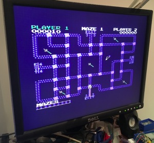
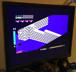
So I could load a reasonable range of cassette based games. Next goal was adding a virtualised floppy controller to the SV-318.