I have a Willem parallel EPROM programmer (or clone). I bought it when I was trying to burn Amiga Kickstarts, but I’ve used it for burning 27C256’s and 27C512’s as well. I’ve had a lot of weird problems with the Willem. Sometimes it ‘just works’. Other times you tear your hair out trying to figure out whats wrong with it. When I bought it, it seemed like the cheapest way of programming the special 16bit EPROMs used in the Amigas.
Recently I was trying to burn a 27C512 to put into my C64C. I got the Willem out, plugged it into my trusty old Thinkpad T42 (it has a parallel port!). I did a blank check. All good. I tried to burn a 32K image … and nope … the Willem decided to burn a solitary ’00’ byte to the first byte in the EPROM … and do nothing more. Now ensues an hour or two of trying to figure out what was wrong. My Willem had blown up its 74HC04 some time back, so I checked the replacement one I put in. It was fine.
Eventually I worked out that the Thinkpad was running on battery (I had plugged it in and forgotten to turn it on. Doh!), and I guess the voltage levels of the parallel port (which are probably marginal to start with) are much worse when running on battery … or at least that was my theory. Once I had it running on mains power again, it burnt the EPROM OK (fortunately I wanted to burn to the top 32K, so the wasted 00 byte at the bottom was not that irritating).
This whole saga got me thinking …. surely I can make my own EPROM programmer. I’d made 2732/2764 type burners myself as a kid and I’d learnt a lot by hacking meeprommer to program flash ROMs. I’d had a brief look at the datasheet for the 27C256 and 27C512 and initially was put off my the requirements to have a 6.5 ish Vcc and a 13 ish Vpp. And the 27C512 has something called ‘margin mode’ …. and well it all sounded too hard.
So I took a crappy approach. Getting the two extra voltages was problem number one. So I already have a 5V supply from the Arduino itself, so to get the other two voltages;
- Used a spare LM2596 adjustable supply I had. So this has 12V in, and a trimpot to adjust the output voltage. Before connecting this to anything I adjusted it so that it produced 6.45V (a 27C512 wants 6.25V +/- 0.25V, and a 27C256 wants 6.5V +/- 0.25V)
- Used a DC boost converter I bought ages ago thinking I would run something off 2 AA cells. This was advertised on ebay as ‘2A booster board DC-DC step-up input 2/24V to 5/9/12 / 28V Replace XL6009 M92’ and cost maybe $1.50. I wired the input of this to the 5V from the Arduino, and before connecting it to anything I adjusted the output voltage to 13V (a 27C512 wants 12.75V +/- 0.25V, and a 27C256 wants 13V +/- 0.25V). In theory I could have used another DC boost converter to generate the 6.45V from a 5V input.
Now, a proper EPROM programmer would have some clever stuff to programmatically switch voltages on the appropriate IC pin. We will cheat here and just move a jumper wire or have a toggle switch (this provides endless opportunities to destroy your EPROMs if you’re not careful). It’s not exactly ideal, but its cheap. We kind of throw out the ability to immediately verify each byte we’ve written (eg. a normal EPROM programmer might go ; write; verify; write; verify … . Instead, our one will just go write; write; write …. and when we’re finished we’ll remove all the crazy extra voltages and just read ; read ; read).
So the general idea is this;
- Wire up the EPROM to the meeprommer address latch stuff so that you can read from the EPROM. ie. Vcc is 5V. On a 27C256, the Vpp pin is tied to 5V. On a 27C512, the G*Vpp pin goes to the A4 pin on the Arduino (also for a 27C256, you want to hook up A4 of the Arduino to OE*)
- Have the 6.5V and 13V PSUs ready to go, but their outputs are not connected (other than connecting their GND pins to the GND of the Arduino).
- When you are ready to write to the EPROM, manually remove the 5V Vcc supply from the EPROM and replace it with the 6.5V supply. I’d suggest you do this quickly.
- After Vcc is changed, remove any connection to the Vpp pin (or G*Vpp pin), and instead connect 13V to the Vpp pin (on a 27C256) or to the G*Vpp pin (on a 27C512). I actually use a toggle switch for this rather than messing with jumpers.
- Run the ‘w’ command to write to the EPROM using an xmodem transfer. It will write away for a while sending the appropriate 100us pulses to CE*
- When writing is finished make sure you 1) Remove the 13V from the Vpp or G*Vpp pin, and set it back to what it was connected to when you are just reading from the EPROM and 2) switch the Vcc supply to the EPROM from 6.5V to 5V
- Run a ‘r’ command to see that something was written to the EPROM. You can also do the ‘m’ command to md5sum a range of addresses and confirm that it matches the md5sum of the file you just wrote to the EPROM.
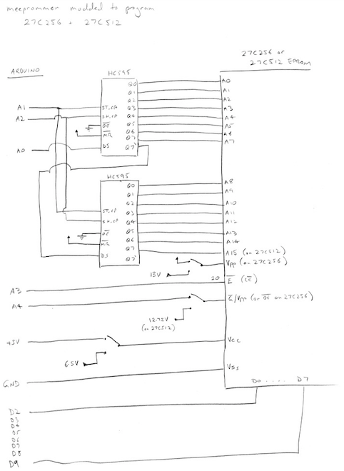
Here’s the rough schematic below. One key thing to point out is that pin 1 is the A15 pin of a 27C512 , but is Vpp on a 27C256. So for a 27C512 you just run the Q7 output of the high address latch to p1. But for a 27C256 you need to run p1 to a jumper or toggle switch to be able to switch between +5V and +13V.
As far as changes to the program are concerned, its actually pretty simple. I removed much of the special flash algorithm stuff and for the 27C256 and 27C512 they just need a 100us pulse on the CE* to write data to the EPROM. I ignored the stuff about margin mode and so far it seems to work OK. I suspect that if it didnt write some bytes correctly that you would just use the ‘w’ command again to have a 2nd attempt. A real EPROM programmer would effectively do that; write; read what we just wrote ; if its not correct try writing again …
I’ve also added a ‘b’ (blank check) command that scans an address range looking for anything that is not an 0xFF. The basic concept with EPROM burning is that you are changing ones to zeros (0xFF is all ones). You can’t change zeros to ones without a UV eraser (or leave them in the summer sun for a week). Hopefully I’ll add some kind of xmodem ‘compare’ mode that transfers the file via xmodem from some other system, but instead of writing it, it just compares what is on the EPROM against what is being transferred (ie. a verify mode).
I also have a ‘t’ test command that will write exactly two bytes to an EPROM. For example to write 0x11 to address 0x00000 and 0x22 to address 0x00001
t 00000 01122
So far I’ve tested the program on 27C256s and 27C512s. It seems to work OK. It’s probably not super quick, but not too bad overall (Apologies, the code is a bit rough. It needs a tidy up)
meeprommer-8biteprom-0.01.tar.gz
Programming a 27C160
(and probably the 27C400 and 27C800)
So burning an 8 bit EPROM like a 27C256 or 512 didn’t seem that hard overall. I wondered how hard it would be to program the 16 bit wide EPROMs like the 27C160. I bought the Willem because I thought it’d be ‘too hard’. Just like the 8 bit wide EPROMs, they need two additional voltages (6.25V and 12.75V) for programming. A complicating factor is the 16 bit wide data bus. I didn’t really want to add heaps more chips to try this out, so how to do this?
These EPROMS have a special BYTE mode that allows you to read the entire EPROM using just the lower D7 to D0 pins of their data bus. The lower ‘bit’ of the address bus in this BYTE mode is actually sent to the D15 pin of the EPROM. So in theory you just need an extra pin to drive D15. However, you cannot burn the EPROM in BYTE mode. You have to write a full 16 bit word at a time. That would require an additional 8 data bits.
So here’s the hardware overview;
- Use the two 74HC595s to drive the A15 to A0 address lines of the 16 bit EPROM (a note here that the pin labelled ‘A0’ on the EPROM is usually wired to ‘A1’ of a CPU since its the lowest bit of a ‘word’ address, but we will just wire it up like the main meeprommer schematic. ie the Q0 output of the low address 74HC595 goes to the pin labelled ‘A0’ on the EPROM and so on).
- As per my meeprommer-am29f040 design, we drive the higher address lines of the EPROM using D10 to D12 of the Arduino … and in the case of the 27C160, we’ll just tie a jumper to its highest address pin ‘A19’ and tie it high or low (ie. you have to manually select the lower or upper 1MByte)
- Chain a 3rd 74HC595 onto the output of the 2nd one (ie. the Q7` output of the high address 74HC595 goes to DS of this 3rd 74HC595). The outputs of this 74HC595 are tied to the D15 to D8 lines of the EPROM
- Now in the meeprommer design, the OE* pins of the two 74HC595s are tied LOW. Thats fine, but for our 3rd 74HC595, we’ll connect it’s OE* pin to the A5 pin of the Arduino so we can drive it high (to tristate the output pins) or low (to enable the outputs). I also put a 4.7K pullup resistor on this pin. ie. after reset the A5 pin may be set as in input pin, and we want it to be pulled high so that we tristate the D15 to D8 lines.
- The BYTEVpp pin of the EPROM is tied LOW initially so that we can read from it.
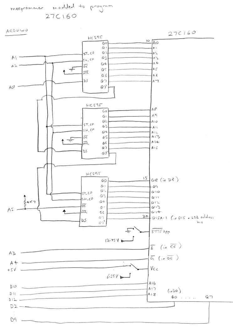
Here’s the rough schematic. The main thing is the extra 74HC595. And note how we drive OE* of the 3rd HC595 from A5 of the Arduino.
So, now the routine to set the address bus needs to first shift in what we want to write to the ‘upper byte’ (D15 to D8), followed by the high and low bytes of A15 to A0.
For reading data, we need to make sure that ‘upper byte’ has bit 7 low or high depending whether we want to read the even or odd byte in a 16 bit word. We also need to make sure we un-tristate the outputs of that upper byte when we are trying to read data. When I first was testing ‘reading’ out I actually tried to use a real mask ROM out of an Amiga 600. This was a bad idea. As far as I can tell, even though the mask ROM has a pin labelled ‘BYTE’, it does not support BYTE mode, and only let me read ‘one word’ at a time. You could potentially do damage here as you’ll have the ‘upper byte’ 74HC595 driving the D15 to D8 lines of your EPROM at the same time that the EPROM itself is trying to drive D15 to D8. Anyway, I warned you; Don’t try and read a 16 bit mask ROM with this thing. Of course, the BYTE mode works fine with my 27C160s.
For burning the EPROM, we shift real data into that ‘upper byte’ that we want written to the EPROM. The low byte of what we want to write goes out via the normal D2 to D9 lines of the Arduino. The main thing to do to write a word is to pulse CE* for 50us. We still need to juggle some power supply connections, but it does indeed work. So essentially the writing procedure is just like for the 8 bit EPROMS;
- Wire up the EPROM to the three 74HC595s so that you can read from the EPROM. ie. Vcc is 5V. Make sure that works.
- Have the 6.25V and 12.75V PSUs ready to go, but their outputs are not connected (other than connecting their GND pins to the GND of the Arduino).
- When you are ready to write to the EPROM, manually remove the 5V Vcc supply from the EPROM and replace it with the 6.25V supply.
- After Vcc is changed, remove any connection to the BYTEVpp pin and instead connect 12.75V to the BYTEVpp pin. I use a toggle switch for this rather than messing with jumpers.
- Run the ‘w’ command to write to the EPROM using an xmodem transfer. It will write away for a while sending the appropriate 50us pulses to CE* (often labelled E* on the datasheet)
- When writing is finished make sure you 1) Remove the 12.75V from the BYTEVpp pin and set it back to GND again and 2) switch the Vcc supply to the EPROM from 6.25V to 5V
- Run a ‘r’ command to see that something was written to the EPROM. You can also do the ‘m’ command to md5sum a range of addresses, but you’ll need to read the note on endian-ness below.
 One other thing to be aware of when writing to 16 bit EPROMs is the ‘endian-ness’ of the data you are writing. Essentially ‘you have to get it right’ otherwise you will have a very useless EPROM.
Here’s an example that might help. If you look at the hex bytes at the start of an Amiga Kickstart rom dump file (do not use ‘hexdump’) it might look like
11 14 4E F9 00 F8 00 D2 ….
ie. the 1st byte of the file is 0x11, the next is 0x14 and so on.
But if you read from a previously programmed EPROM , it might look swapped
14 11 F9 4E F8 00 D2 00 …
Essentially what is happening when reading is that the first byte shown (14) is what would be in D7 to D0 of the first 16 bit word, the next byte (11) is what is in D15 to D8 of the first 16 bit word. To something like a 68000 CPU the data at D15 to D8 will be effectively at the lower address, and the data at D7 to D0 at the next higher address .. so it is sort of backwards to the way our reader reads things.
The main thing to know is that I have a flag in config.h (LITTLEENDIAN). Set it to ‘false’ for a Big-endian CPU like a 68000. Set it to true for a little endian CPU. The flag is only used for writing data. Reading is always done in byte mode and ignores whatever. An alternative is to set LITTLEENDIAN to true and remember to byte-swap the file before you transfer it with xmodem.
You’ll have to byte swap the file anyway if you want to do an md5 check to confirm that what you wrote to the EPROM is actually there. I use dd;
dd conv=swab if=kick.rom of=kick-byte-swapped.rom