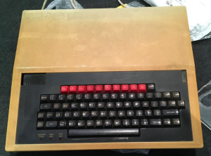
I recently bought a BBC Micro Model B. It sold ‘as is’ and I had no idea if it worked. The case was very yellow. It came with a 5 1/4″ drive, cassette player, several books and original versions of Elite on disk and cassette. It did not work, and ended up having a number of faults
Having never owned a BBC Micro, when I first picked it up, I did a search to see what sorts of things tend to fail. A common fault are the RIFA capacitors in the PSU. Apparently these can explode a bit, and given I live in an apartment, I thought it might be smarter to replace them first.
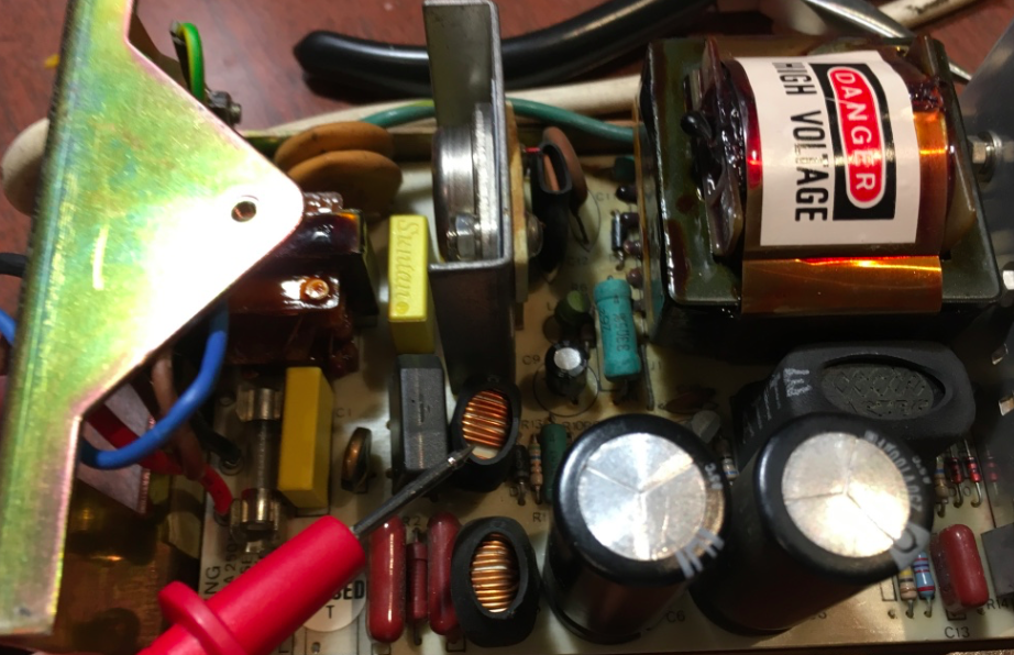
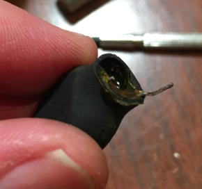
I replaced the RIFA caps as well as C9, the 220uF electrolytic (also recommended to be changed). I powered on the PSU only. It measure maybe 0.8V to 1.V on the 5V output. I ended up replacing a lot of the electrolytics, until I happened on this post . It shows a picture of one of the coils in the PSU with one leg broken due to ‘metal fatigue’. Some poking around later, I found exactly the same one legged coil. I desoldered it. It has some heatshrink tubing around it and it’s also been dipped in resin. I was able to cut at some of the resin at the bottom of the coil. This revealed enough of the remainder of the broken leg. I could then ‘just’ resolder it back in. Power on the PSU, and I finally had +5V (as well as -5V, and +12V).
I then hooked up the motherboard and powered on. I don’t think I got a picture at all. I ended up pulling out chips and putting them back in. If anything there seemed to be a lot of oxidation on pins and sockets. At one point I took a Fairchild 6845 from my parts bin, and swapped it for the Hitachi 6845. Powered on, and I got a picture that at least had some sync and what looked a bit like a valid image somewhat repeated (I can’t remember exactly). At that point I swapped back in the Hitachi 6845 and got what looked like a working system.
I also swapped IC14 (74LS245) as I’d read it often fails. It is socketed, and I have plenty of spares.
Then I noticed that many of the keys did not work. I powered off and started to remove some of the mechanical keyswitches. You can pretty much just use wick to desolder each keyswitch, then whack the two pins from the the reverse side , and the switch should pop out. You then have the individual keyswitch with the two pins sticking out. Get some long nose pliers, grip each pin in turn and give them a few twists, and they will unscrew. With both out, the whole keyswitch falls apart, and you can inspect and clean the mechanism inside. I’d say I had 10 or more keyswitches that did not work or were marginal. I put it all back together, and powered on; nothing!
Yeah, no picture again. I went down the path of looking at IC3 (6522) and IC26 (74LS259). I went so far as desoldering the 74LS259, and socketing it, but that did not help.
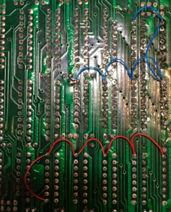
Eventually I noticed the base of the keyboard 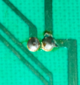 circuit board. In the process of removing lots of keyswitches, I must have repeatedly bumped the three LEDS in the bottom left corner. I could see that the GND line PCB trace to one of the LEDs had lifted off a bit, causing a break. I repaired the break, and I had a picture again.
But when I switched MODE, I just got a cursor. I thought ‘maybe DRAMs’. On my Issue 4, eight DRAMS are soldered in, and eight are socketed. I took some of the socketed ones out and tried testing them in a arduino based dram tester . Almost all of them failed in my tester.
Now the BBC uses 16Kx1 5V DRAMS (aka 4816’s). These are not as common as the multivoltage 4116’s. But a 4816 is almost the same as a 64Kx1 4164. I have spare 4164’s, so I decided to modify the circuit board to allow me to put 4164s in. I tied pin9 (A7) low for all sixteen DRAMs.
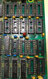
It seems like a waste as sixteen 4164s now gives me 32KB , not 128KB. But it was easy to change. I also desoldered all the eight soldered 4816s, and put sockets in.
Powered on again with 4164s in it, and the behaviour was strange. Only one 16K bank would work at a time. If I had S25 North, it would not boot. But it would boot with one of the 16K banks enabled. These are the 3 possible settings
- S25 North (ie. towards the back of the board) means both the lower and upper 16K banks are enabled. This did not work for me.
- S25 South means one of the 16K’s is active only. This worked
- S25 removed entirely means the other 16K bank is the only active one. This worked.
I pondered how on earth this was possible, as it seemed to have booted OK in 32K mode before with broken-ish DRAMs. I assumed I had damaged something while desoldering. After several on/off events later I found it no longer powered on at all. Just a continuous speaker tone.
So I did the obligatory searches for ‘continuous tones BBC Micro’ and got nowhere. Eventually I soldered an 8 pin header to one side of IC14, so I could easily attach my logic analyser to see what was going on on the data bus.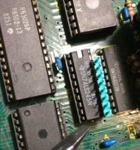
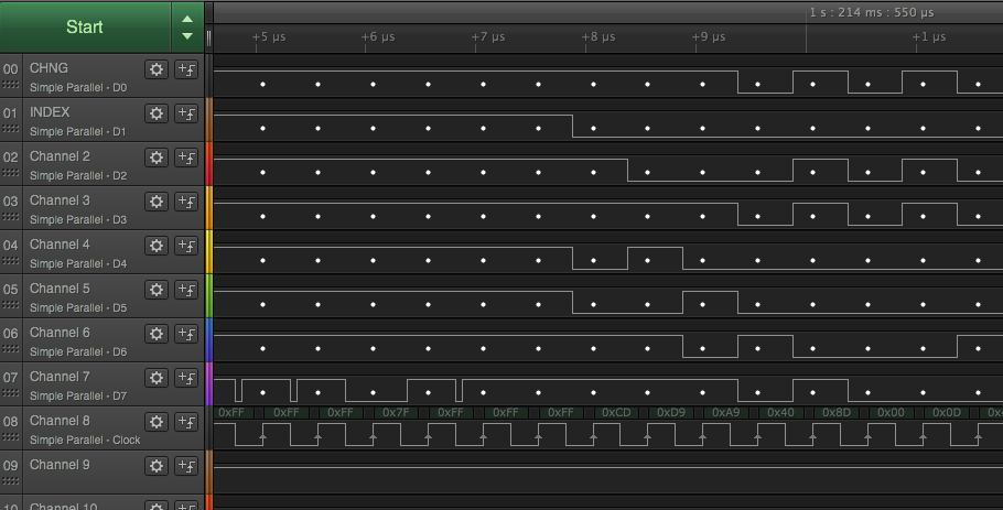
I hooked up my logic analyser so it could see the 8 data lines (on the CPU side of IC14), as well as RESET* and phi1 (p3 on the 6502). I powered on and off a few times, and got nothing resembling a boot. You should see 0xCD, 0xD9 as it reads the Reset vector, but I just seemed to get some random stuff.
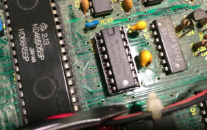
I hooked the logic analyser into the CS* (p20) of the OS ROM, and it seemed to be OK. But then I looked at the OE* line of the OS ROM and it was not going low at all. The OE* signals of all the ROM sockets are fed from one gate in IC25 (74LS20), with most of its inputs coming from part of IC20 (74LS139). When I had a closer look at IC20, it looked like the outputs weren’t working properly. Pin 6 seemed to be stuck low.
I desoldered IC20 and socketed it. 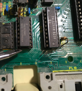 It is easy to test a 74LS139 in a breadboard, and on the left hand side of it, p6 was always stuck low, so I put in a replacement 74LS139, and it now booted up OK, and more importantly it seemed to boot in 32K mode.
Here’s a snippet of what you should see a bit after RESET* goes high as it reads the reset vector and executes the first couple of instructions . A9 40 is a LDA immediate $40 at address D9CD. (NB: Ignore the CHNG, INDEX headings. That was just leftover from the last time I used my analyser). The top 8 traces are the databus lines. Channel ‘8’ is phi1 (pin3 on the 6502), and Channel 9 is my RESET*. You would have to scroll some way to the left to see where RESET* went high.
But alas, when I entered a MODE command to change from the default MODE 7, I just got a flashing cursor or repeated bits on the screen. So MODE 7 worked, but none of the bitmap modes worked properly. I had a look around the 74LS283 adder that is used to compute an offset for all the bitmap modes (MODE 7 is the only non bitmap mode). After hooking up my logic analyser to the inputs and deciding they looked OK, I looked at the output of the adder and it just looked a bit random in the bitmap modes (anything but MODE 7).
 I’d actually already ordered some 74LS283’s on ebay thinking it might be a cause of some of my failures. I desoldered the one on the BBC motherboard, socketed it and replaced it and amazingly it all pretty much worked for the first time since I bought it!! I could enter MODE 1, MODE 2 etc and it all worked.
However, some of the keys (especially return) were having a hard time working. I had desoldered the return key and a few others to clean then before, and I thought they were working OK. But they were still intermittent. Again, I got the logic analyzer out to see some of the signals on the chips on the keyboard circuit board. They seemed to be working OK. I thought maybe the column that the return key is in was bad, as return, copy and some of the arrow keys did not want to work all the time either.
But at least one of the cursor keys did work well in that same column. I traced the PCB traces from pin 11 of the 7445. Eventually I found an open circuit between two of the keys. 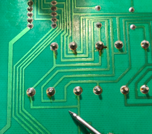 I inspected it under my illuminated magnifying lamp and it looked fine. But I resoldered the keyswitch legs between this pcb trace … and suddenly it was no longer an open circuit. I guess it had a dry joint … which is almost amazing for a low voltage environment like a keyboard. I guess if you hit keys hard enough you create fractures over a long time in a mechanical keyboard like this.
So was that all? Well, I then finally hooked up the 5 1/4″ floppy drive that came with it. It did indeed spin, and the head moved, so that was all good. But any attempt to format a floppy failed. The Beeb only came with one floppy disk; an original of Elite, and I didn’t really want to damage that. So the floppy drive requires more investigation. However, I do have a few gotek drives with HxC firmware, and I know they read BBC Micro disks OK.
So I downloaded some BBC games in .ssd format. You have to convert them to HFE format first using the HxCFloppyEmulator program. There are notes on the settings on the stardot forums. You need to choose ‘Load Raw Image’, and these are the settings I used;
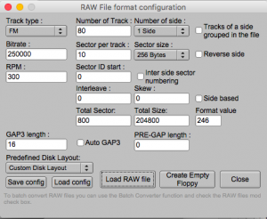
You then copy your HFE files to a USB stick, and make sure they are called DSKA0000.HFE, DSKA0001.HFE and so on. Then make sure you put the ‘Indexed mode’ HXCSDFE.CFG file on the root of the USB stick.
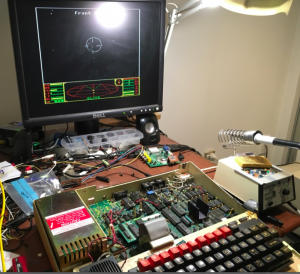
After some research to work out how on earth you load a game on a BBC Micro (shift-break) I was loading Elite, and it worked! Here is the obligatory screenshot (apologies for the light reflection from my magnifier lamp);
So now that it’s finally going;
- Elite works really well. So far as 8 bit versions of Elite, it’s probably one of the better platforms to play it on.
- I find the screen output quality is marginally worse than the Electron. Might have to investigate that. Basically I am running the RGB output into a Gonbes.
- I am quite impressed with the games, so far as playability and speed is concerned. Sure the colours can look a bit weird, but it’s pretty good overall considering the chips in the Beeb