UPDATE (20190523). There is a ‘Part 2’ of this article in Acorn Electron ROM Emulation with an STM32F4 that describes using interrupts to emulate ROMs. The article below involves using ‘polling’ to perform a similar function.
I remember reading dhole’s Emulating a GameBoy Cartridge with an STM32F4 some time ago thinking that it had a lot of applications with respect to old computers. In that article a STM32F4 microcontroller ‘pretends to be a ROM chip for a gameboy’. At the start of a bus cycle, an interrupt is triggered in the STM32F4, it then reads the address bus of the gameboy’s 6502, checks the gameboy’s read/write line(s) and pulls data from its internal Flash and presents it onto the data bus long enough for the gameboy to read it, then tristates the databus. There are no wait states. It does this all within the 1000ns of the 1MHz Gameboy CPU clock. For all intensive purposes the gameboy thinks it has a real rom chip attached.
The STM32F4 is a good candidate here as it has a lot of GPIO pins, and they are pretty much all 5V tolerant. The clock speeds sound good too; 168MHz+, and there is plenty of Flash storage onboard, and you can get really cheap STM32F4 boards on eBay/aliexpress.
Anyway, I thought I’d see if I could turn an stm32f4 board into an ‘Electron Plus 1’ expansion for my Acorn Electron. That way I could add ROMs, and potentially an SD card interface that would let you load floppy images.
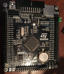
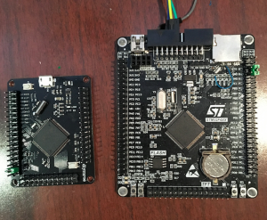
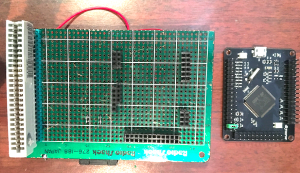
I have this black stm32f407VET6 board that costs about US$10. It has lots of GPIO pins and a Micro SD slot. (excuse the thin blue wire. That is me reconnecting a trace that I cut in an earlier experiment).
So dhole ran the 1MHz Gameboy clock into PC0 on the stm32f4 to generate an interrupt. Everytime I attempted to do this on the Electron, I found the stm32f407 was taking a good 200 to 300ns to respond to the interrupt. I tried lots of different things thinking surely I had done something wrong for it to take so long, but I could not figure out how to get it much better. I did learn a lot about the stm32f407 while trying to figure it out though. 1. The ART accelerator for running programs from flash is pretty good and 2. You cannot run programs at all from CCMRAM. The clock cycle of the Electron during a ROM access is 500ns (2Mhz), but I had the goal to service everything in the 250ns from the positive edge of the phi0 (Ï•0) clock to the negative edge of phi0. When phi0 goes high, the address bus and read/write line is stable, so you don’t have to wait a certain number of NOP instructions for certain events to occur.
Of course the problem is that you only have 250ns.
I gave up on using an interrupt and ended up just polling for the positive going edge of phi0. I found I could detect the positive edge in about 70 to 90ns. That is a lot better than the interrupt approach.
I also started off doing this in C, but soon figured out I would need to do it in ARM Assembly to be able to fine tune the timing. A summary of my ARM Assembly effort;
- I had written a lot of 6502, Z80 and 68000 assembly ‘back in the 80s’. However, I had not looked at any assembly for quite some time.
- I did not know any ARM assembly.
- I originally started looking at the disassembly of my C code and tried copy/pasting stuff. This turned out to be stupid.
- I eventually found Joseph Yiu’s ‘Definitive Guide to the ARM Cortex M3’ (NB: This is an excellent book) . That solved most of my ARM assembly problems.
The code basically does this ;
- Overclock the board to 200MHz. This just makes the timing a little better.
- Turn all interrupts off
- An unrolled polling loop looks for the positive edge of phi0
- When phi0 goes high, grab the 6502 address bus and read/write line.
- Detect whether its a ROM access or an IO register access ‘above $FC00’
- If its a ROM access, I look up the appropriate ROM address and untristate the data lines, present the data, and wait for the negative edge of phi0. As soon as it goes low, I have to tristate the databus again as fast as possible. Up to four ROMs are ‘compiled’ into the flash image that you flash to the stm32f4. These will show up as ROMs 12,13,14 and 15 to the Electron.
- For an IO register access, I have a big jump table using the TBH instruction to manage any IO space attempt above $FC00. This way it is ‘constant time’ to detect the IO accesses at $FC71 (Electron Plus 1 output port), $FC72 (Electron Plus 1 busy input) and $FE05 (sideways rom select) … and potentially others if I want to add other stuff in.
- For writes to the sideways rom register, I just store the rom number in a ARM register.
- For writes to the $FC71 port, bits D0 and D1 are ‘passed through’ to PD2 (MOSI) and PC12 (SCK) on the SD card adapter.
- For reads from the $FC72 printer status port, we read PC8 (MISO) and then present it as D7 to the 6502. This isn’t quite how a real Electron Plus 1 printer status port works, but it is good enough for MMFS to work.
- For the $Fe05 and $FC71 ‘writes’, we go into another unrolled loop to wait for phi0 to go low.
- Loop back to the top and wait for phi0 to go high again.
So essentially we ‘mimic’ the $FE05 sideways rom register and ‘pass through’ the $FC71 and $FC72 IO ports in an Electron Plus 1 to the SD card adapter on my stm32f407VET6 board. If the sideways ROM register is set appropriately, and its a read between $8000 and $bfff, we read the copy of a ROM from flash and present the appropriate byte to the 6502A.
Here’s a logic analyser snip of the delays surrounding ROM accesses. The top trace is the Electron’s phi0. The bottom is PA0. There are a few defines in the code that allow you to toggle PA0 to get a rough idea of timing. Below is with DEBUG_ROM set. It will set PA0 high when it knows its a read from the ROM address range, and then set PA0 low once a byte has been pulled from flash and presented to the 6502A. It’s not entirely accurate since you waste a few cycles just setting PA0. So the snip is showing that I am taking about 80ns to figure out its a ROM access, and another 110ns before I can get something on to the bus. The data will sit there for (at least) another 50 or 60ns, before the bus needs to go tristate.
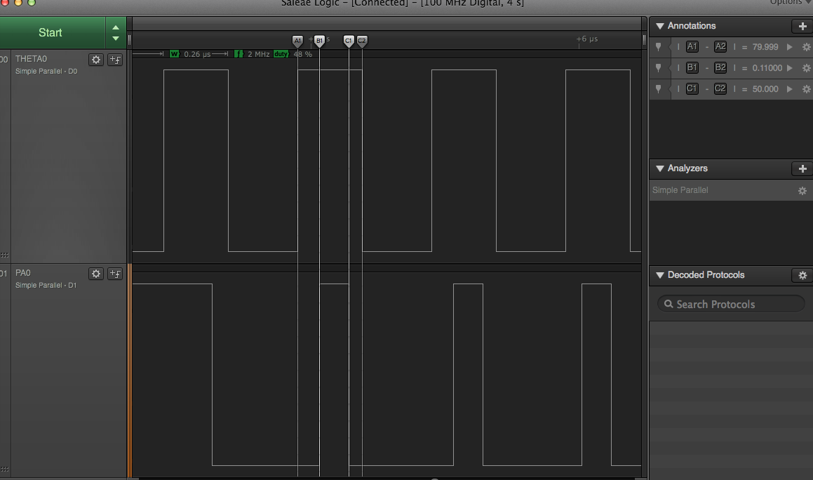
Accesses to the sideways ROM register and the Plus 1 IO ports is a little different as the phi0 clock is stretched by the ULA for those (ie. they are not as time critical as the ROM access code).
Before you compile the code you’ll need some ROMs for an Electron. You could google around for some. Just make sure they are Electron ROMs, and ROMs as in ‘an image of a 16KB ROM chip for an Acorn Electron from back in the day’. If you just want to use MMFS, then go to the MMFS release page . Grab the latest one, and find the main Electron MMFS ROM. It should be in
build/E/EMMFS.rom
Copy that into the ‘roms’ directory (NB: I usually recompile/reassemble MMFS with the option to enable the *ROMS command, as it’s really handy when troubleshooting). If you look near the top of the poller.S file you should see a few .incbin lines. The one for EMMFS.rom is most likely uncommented (ie. the default is to have one single sideways ROM in slot 12 being MMFS). If you want to add more ROMs, just put a few more .incbin lines specifying the rom in the roms directory. Right now, the code only supports four ROMs; ROM 12, 13, 14 and 15.
I’ve set this up to compile using a Makefile. I am highlighting this as I was a bit of an STM32 noob when I started working on this, and it’s often confusing trying to figure out whether you need Keil or Eclipse or whatever to compile someones code. The main thing you need is for arm-none-eabi-gcc to be in your PATH. For example, I have all the ARM build chain stuff in a directory under /usr/local;
export PATH=/usr/local/gcc-arm-none-eabi-7-2017-q4-major/bin:$PATH
You also need some STM32F4 includes from st.com. You can use the STM32F4 Discovery ones or the more general STM32F4 DSP StdPeriph ones. This effectively gets you the ‘Standard Peripheral Library’. Look at the STM_COMMON reference in the Makefile, and change it to the one you have.
Then just ‘make’.
You should end up with an elf, hex and bin file.
If you’ve never programmed an STM32 board before, there are a few ways. A simple way for me is to use dfu-util (though more recently I am using a FT2232H as an openocd interface). If you search you’ll find howtos for Windows and Linux and OSX on how to get dfu-util installed. The key thing is set the BOOT0 jumper shorted to 3.3V, then hook up a USB cable from your PC/laptop to the board (ie. it powers on with BOOT0 High). Then run dfu-util to send the compiled bin file to the board (see the transfer.sh file in the source). Now remove the BOOT0 jumper (or set it back to being connected to GND).
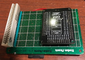
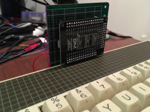
Here it is all wired up to my Electron.
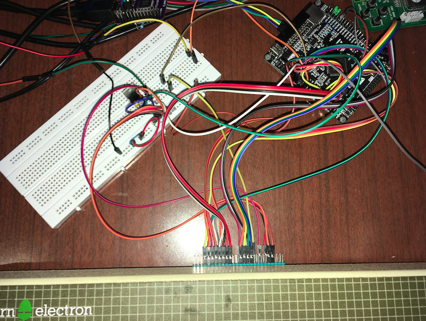
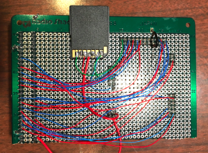
It’s a mess of jumper wires at the moment, but I think this is a ‘not so hard’ piece of hardware to hack together. Essentially I have soldered some header pin strips to the back of a 50 pin edge connector.
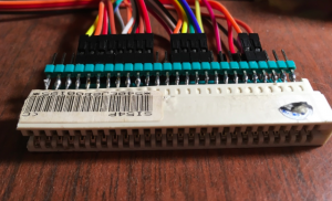 Then run jumper leads to the STM32F4 board. That’s pretty much it.
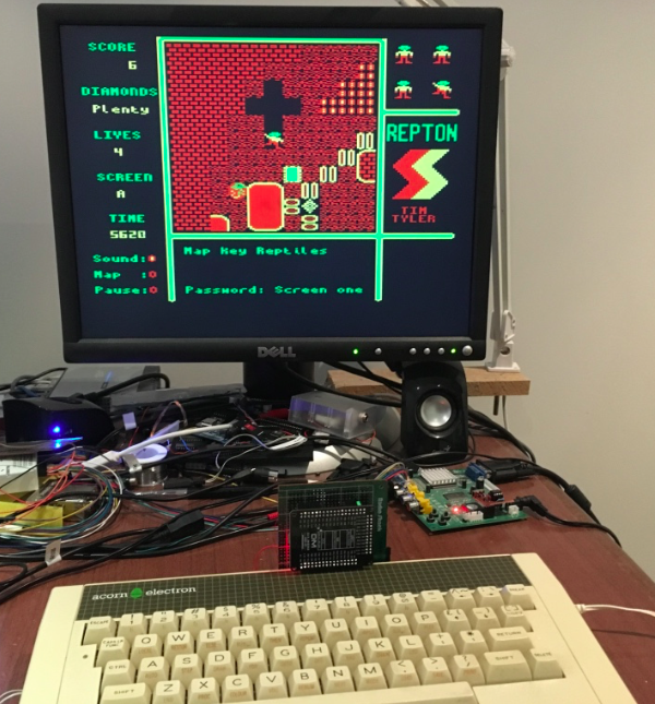
The breadboard in the earlier photo is used for a LM1117 3.3V regulator. The stm32f407VET6 board has it’s own 3.3V regulator on it, but whenever I feed the 5V from the Electron into the 5V pins on the stm32f407VET6 the SD card initialisation never works. The ROM emulation works though (you can see the ‘MMFS’ banner on the Electron). As a sidetone, I’ve also been working on doing this same sort of ROM emulation for an Amstrad CPC 464, and having nice stable power for the SD Card initialisation is really critical.
You can also just leave the LM1117 out and power the stm32f407VET6 board from a USB cable. I always seem to get ‘nicer’ stable power via a USB cable.
Wiring details are in the README.md ,but the broad overview is
- D0-D7 go to PD8-PD15
- A0-A15 go to PE0 to PE15.
- phi0 goes to PC0
- _R/W goes to PC1
- GND to GND
- See the earlier notes about power supplies for what to do with +5V
If you are using MMFS, you need a FAT32 partition on the SD card (actually, go read the instructions for setting up MMFS). I am not sure if its required, but I would put the first partition on the card as ‘less than 4GB’, and then format that partition. I just did a mkfs -t vfat on a linux box for mine, but you will see recommendations all over the net for the ‘Panasonic SD Card Formatter’ for formatting SD cards used in most embedded projects.
Inside this FAT32 partition you probably want to put a BEEB.MMB file (one for an Electron, not a BBC Micro). I just used the BEEB.MMB from this stardot.org.uk thread.
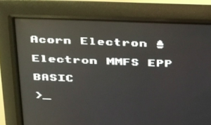
With everything hooked up, power on and you should see ‘MMFS’ in the banner at power on. If you don’t see it, try reseating the edge connector. I have had plenty of cases where the edge connector was not lined up properly (and it wouldn’t hurt to clean the contacts of the edge connector as well).
There’s probably more info on using MMFS on it’s github page, but if you have the BEEB.MMB on the SD card, you can do a *DCAT :
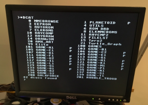
And you could load something manually using the *DIN , *DRIVE and CHAIN commands
An alternative is to use the MMCBROWSER. Power on the Electron and enter:
*EXEC!BOOT
Which will start a MMCBROWSER program to be able to load disks out of the BEEB.MMB file
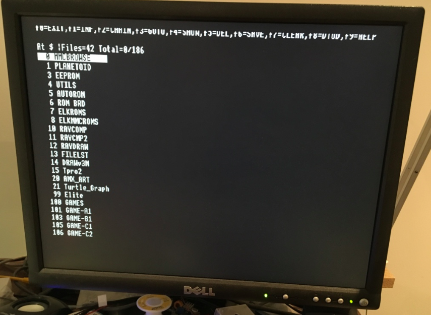
I am not entirely sure how you are meant to use MMCBROWSER, but the following works for me;
- select a disk with the cursor keys
- press f8 ( or FUNC 8 on an Electron)
- Choose drive 2
- press f0 (FUNC 0)
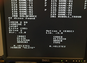
- Enter *DRIVE 2
- Enter *CAT
- You should see a list of files on a virtual disk.
- Enter CHAIN “NAME_OF_THE_MAIN_PROGRAM_ON_THE_DISK”
- Enjoy
Often the hardest part is guessing what to put for the CHAIN command.
Just as I was finishing writing this up, I got one of the cheaper stm32f407VGT boards in the post. They are only $1 cheaper admittedly, but I thought the design might lend itself better to making a more permanent solution. They are a lot smaller than the Black VET6 board, and have no SD slot.
I found a reference to a schematic of the VGT6 board on the stm32duino forums. There’s not much to it. The part labelling in that schematic doesn’t exactly match my board, but it’s close enough. One modification I did to the board was to remove the R3 resistor next to LED2. In the schematic it’s actually labelled R2, but its connected to PE0. I connect PE0 to the 6502A A0, and I did not really want it having to drive an LED as well.
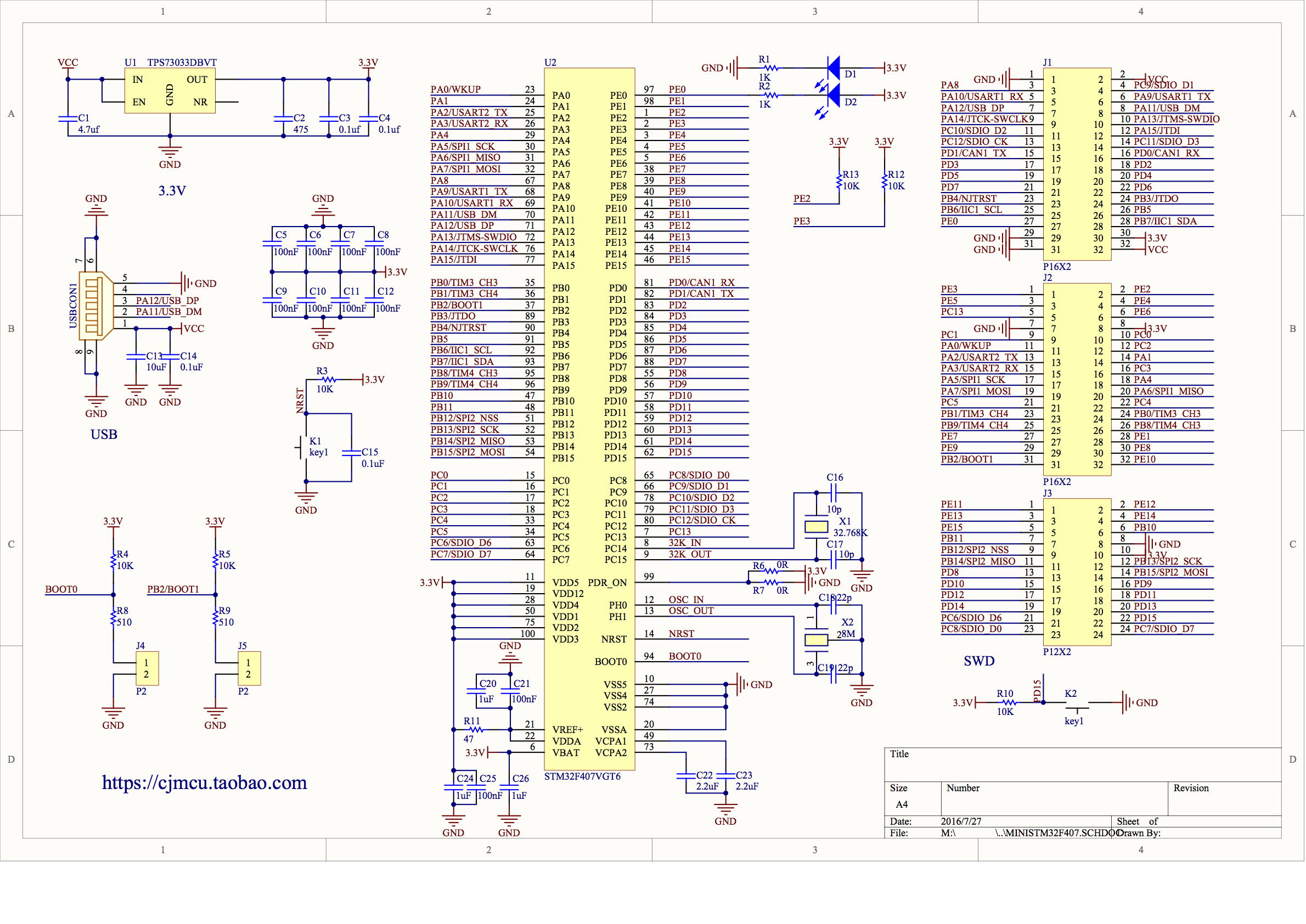
So I chopped up some (very) old protoboard and made a sort of carrier board for the VGT6 board. I was trying to save on pin header socket things, hence the funny layout. And I just used a full SD to micro SD adapter (that you seem to get with every micro SD card you buy).
And assembled:
I’d probably change the position of the SD card adapter if I did it again. It is awkward to change once you plug it into the Electron.
One good thing is that if I feed the Electron +5V to one of the Vcc pins of the VGT6 board it all works OK (ie. SD card initialisation works). You have to be a bit careful though if you want to reprogram the board with Vcc tied like this. You will end up powering up your Electron from the USB cable.
Source:
https://github.com/kernelcrash/electron-rom-emulator