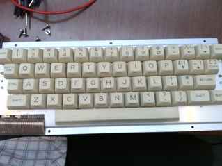
For the past few months I’ve had two Acorn Electron’s. One is a fully working one I bought from the UK earlier in 2015. The other is my brother’s one which was broken. I thought I would attempt to fix it … but all I’ve confirmed is that it has a very dead ULA. Spare Electron ULA’s are not that easy to come by. Given that my brother isn’t exactly pining for a working Electron, I thought I’d try turning it into a USB keyboard. The Electron has quite nice real mechanical keyswitches.
 I’ve recently been looking at various VUSB projects. VUSB is a small software based USB stack for AVR microcontrollers. You can’t do USB host mode (eg. plug a USB mouse into an AVR) , but can make USB keyboard, mice and some other devices. I’d recently bought some plain Atmega328p chips and thought I would have a go at using VUSB with the Electron.
Of course I searched around for another ‘VUSB for Acorn Electron keyboard’ project, but the closest I could find was the c64key project. That converts a Commodore 64 keyboard into a USB keyboard using vusb. The C64 keyboard is a (almost) 8×8 key matrix. The Electron is 14×4. There is a nice reference to the keyboard in the Electron Service Manual.
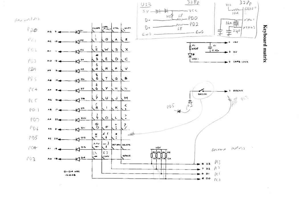
The circuit diagram is like a like a lot of AVR circuit diagrams; more of a what is connected to what. And yes it is crappy and done in a hurry. But you’ll figure it out (one thing missing is the 100nF ceramic across VCC and GND somewhere. Not sure if you need a 4u7 electrolytic somewhere as well, and I just use two 1N4148’s to drop the 5V on its way to the 328p)
 Ultimately, the c64key code after much hacking and slashing morphed into the electron-keyboard-0.01.tar.gz code I ended up using. So I used a Atmega328p, rather than an Atmega8 or Atmega16. I also used a 16MHz crystal (because I had one) rather than a 12MHz crystal.
One of the more difficult bits of this project was the Electron ‘break’ key. It is pretty much where you expect the backspace key to be, so the obvious thing is to make it the backspace key. Now, it is not part of the 14×4 key matrix. Its actually out on its own. I guess the assumption is that its wired to RESET or NMI or IRQ in the real Electron. When you press it, the button shorts to GND. I could have just wired into it like this if I had any spare GPIOs on the 328p … but I used them all up. So my original idea was ‘force’ it into one of the unused gaps in the Electron key matrix. There is a gap on the row containing ‘minus’, up arrow and colon so initially I sort of wired it in there . Pin 1 of the keyboard connector (physically towards the ‘Esc’ key end of the keyboard, and marked ‘Break’ in the circuit diagram) would go to PC3 on the AVR (one of the ‘column’ inputs) and the 0V line that is meant to be tied to GND for keyboard would actually go via the diode to PD5 on the AVR (the row strobe for this row). I wired the cathode of a 1n4148 diode directly to PD5 (ie. similar how the other diodes are wired. It may seem weird wiring an output directly to the 0V line of the keyboard … but ultimately the 0V line doesnt really go anywhere.
 That sounded like a plan. However everytime I hit break, the keyboard registered a ‘minus’, up arrow and colon all at the same time. Essentially all 4 keys on the same row were registering when I hit the break key. The culprit I think is the 0.47uF cap shown on the Electron circuit diagram. I am not sure why it is there, but in a convoluted way it ends up being part of a RC charge circuit when you press Break, such that the other keys falsely register a keypress while the cap is charging. At least that’s my theory. I tinkered with various electronic attempts to fix this … but I ended up (as a crappy but workable solution) to change the keyboard scanning routine so that if if detected the Break key pressed that it guaranteed that none of the other keys in that row appeared to be pressed. ie. When PD5 is strobed LOW to scan that row, if PC3 is found to be low, PC2, PC1 and PC0 are effectively forced to be high regardless of their state. It seems to work fine.
Like a lot of projects you get 90% of the way to the end and it’s difficult to finish the last little bits. In my case the last little bits are how to handle things like Function keys and what to do about caps lock and what about all the keys that aren’t actually on an Electron keyboard. For now;
- caps lock/fn no longer works as a caps lock. There is no caps lock key effectively
- caps lock/fn is mapped to Left Alt but in general does nothing that an Alt key does. I just wanted the key scanning code to register it as a modifier … which then allowed me to remap fn+1, fn+2 etc so that they would register as function keys. This isn’t actually ideal as a common use of the function keys on linux is holding down alt+f1 or alt+f2 to select linux console screens. So there is no way of pressing alt-f1 given you have to press alt just to get a regular f1. Possibly using ctrl to select the function keys would be a better idea.
- Copy key? Not sure what to do with that one. Ideally you want it to produce a unique key code just incase you do run a real Electron emulator.
- PageUp/Down. Yeah, the Electron doesn’t have those. But they would be handy to map to somewhere on the keyboard.
Anyway, just compile the code with ‘make’ and then run avrdude or similar. Here’s what I do and the fuse settings I used;
avrdude -P /dev/ttyUSB0 -b 19200 -c avrisp -p atmega328p \
 -U flash:w:main.hex:i -U lfuse:w:0xff:m -U hfuse:w:0xd7:m
One diversion I had towards the end of this project is just how easy it is to use bootloaders with these AVRs and vusb. The BootloaderHID example on the vusb site is all you need to make it so you no longer need an AVR programmer to update the firmware. In the bootloaderconfig.h file you just need to make sure USB_CFG_IOPORTNAME, USB_CFG_DMINUS_BIT and USB_CFG_DPLUS_BIT settings are correct, and that you put something useful in the bootLoaderInit() and bootLoaderCondition() routines. The latter is what decides whether your AVR goes into bootloader mode at boot. The example that comes with BootloaderHID just checks if PD3 is low. So, when you power on your AVR with say PD3 high, the bootloader effectively exits and just runs your vusb Acorn Electron keyboard code. If PD3 is low, then the bootloader kicks into action and waits for a intel hex file to be transferred using the ‘bootloaderHID’ command line utility. It’s amazingly easy to get going. The hardest part I found was just working out some of the settings in the bootloaderHID firmware Makefile. The key settings for me with my Atmega328p @ 16MHz were
DEVICE = atmega328p
 BOOTLOADER_ADDRESS = 7800
 F_CPU = 16000000
 FUSEH = 0xda
 FUSEL = 0xff
(Note; if you’re like me and got confused by the 7800 because when you used some online fuse calculator that didn’t have 7800 as an option, you have to remember that 7800 is a byte address, whereas something like $3c00 is a ‘word’ address and actually the same as byte address 7800)
So, sensing that PD3 is low to put it into bootloader mode is very simple, and I wanted something cleverererer. ie. have it so you hold down some keys when the keyboard powers on as the trigger for boot download mode. Must admit, I tried this (the code change seems simple; you set an output pin on one of the rows like PB0, then look for multiple lows on PC3-PC0 … but it never worked. Very weird. Not sure if the bootloader is so tight on space or doesn’t like me setting output pins. For now, I just have it check that PB3 is low … since I have a header pin there (for my ISP to hook in). I just tie that low, plug in the keyboard and run the bootloaderHID.
So I’ve included the bootloaderHID code
cd electron-keyboard/bootloadHID.2012-12-08/firmware
make
You’ll also need to compile the PC side firmware transfer program
cd electron-keyboard/bootloadHID.2012-12-08/commandline
make
# Obviously change the avrdude line to suit your type of programmer
avrdude -P /dev/ttyUSB0 -b 19200 -c avrisp -p atmega328p \
 -U flash:w:main.hex:i -U lfuse:w:0xff:m -U hfuse:w:0xda:m
Now you can just power off the electron keyboard, tie PB3 low and plug it in. On my linux box I then get messages like;
Dec  2 23:18:33 inc kernel: [93916.360461] usb 1-6: Product: HIDBoot
Dec  2 23:18:33 inc kernel: [93916.360462] usb 1-6: Manufacturer: obdev.at
That means its ready and waiting for a hex file to upload to it.
Assuming you did a ‘make’ earlier on the main electron-keyboard code;
cd electron-keyboard
bootloadHID.2012-12-08/commandline/bootloadHID main.hex
You should see some messages about transferring, then unplug, remove the wire holding PB3 low and power on again. All going well you should get these ‘messages’ and have the device detected as a keyboard again.
Dec  2 23:19:25 inc kernel: [93968.694434] usb 1-6: Product: Acorn Electron
Dec  2 23:19:25 inc kernel: [93968.694435] usb 1-6: Manufacturer: kernelcrash.com