After getting the fast RAM and IDE interface all working on one of my Amiga 500s, it gets a bit annoying trying to find the correct boot floppy that has all the correct partition settings in a mountlist. I actually don’t mind the slightly slower boot with the floppy, but the convenience of ‘auto boot’ would be handy.
It’s probably hard for youngsters to understand how it’s even possible to have a computer that won’t autoboot off a hard drive, but you have to think about the context of era. In the late 80s and early 90s when the Amiga 500 was popular, you did indeed have hard drives available … but the cost of one relative to the cost of an Amiga 500 was very high such that most Amiga users got by with one or two floppy drives (this probably varies a bit from country to country). And most hard drives needed a custom controller as IDE wasn’t yet as common as it would end up being. Logically there was not much economic value for Commodore to integrate a hard drive controller into the Amiga 500 if the target market was tiny. Of course this all changed in a few years when Commodore came out with the Amiga 600 and 1200 in 1992. They did have an onboard hard drive interface and an (optional) internal 2.5″ IDE hard drive … as well as a newer Kickstart that would boot from the hard drive. I should point out too that most Amiga 500s came with Kickstart 1.3 … and in theory you could boot from an external hard drive so long as your hard drive expansion had the appropriate ROMs.
Let’s ignore Kickstart 1.3 for a moment. In the Amiga 500++ with my fast RAM and IDE interface on it I have Kickstart 3.1. That Kickstart can autoboot off a hard drive that works with Amiga’s scsi.device. Interestingly, scsi.device is designed to talk to the IDE interface in the Amiga 600 and 1200 amongst other interfaces. The IDE interface that I had is broadly ‘the a500ide one’, which is either this or this .. but I configured it to use a different address (0x700000). It does not work with the Amiga scsi.device (even if it was at the same address). There are other projects out there like ide68k that have a CPLD that implements the logic that scsi.device is looking for … and hence should work with scsi.device.
In my case I had been using an ide.device (i think it is from rkide.lha inside a500ide) loaded off a floppy drive up to this point. It actually worked pretty well, and I’ll note here (as it is relevant later in this post) that I was able to use HDtoolBox from Workbench 3.1 with it. And because there are a few projects that implement this simple IDE interface there are in fact a few ide.device drivers floating around the net that I can use.
Anyway, ideally we want ide.device in our Kickstart and to make it do what scsi.device would normally do to autoboot the Amiga. This means creating a ‘custom kickstart’. Even though Kickstarts are ‘in ROM’ (I’ll gently ignore all the other possibilities for now), they are a collection of device drivers and libraries packaged up in a specific way. There are tools that let you extract out all the device drivers and libraries into files and those tools often let you ‘assemble it all back together’ to make a new ROM. A really useful page I found was an issue logged against the A500_ACCEL_RAM_IDE project . It too is yet another ‘simple IDE interface (plus other stuff) that uses some version of the ide.device driver’. That issue refers to the AIDE project ide.device driver that does contain an ide.device, but also a bootide.device driver too that is required for autoboot to work.
Cool stuff. That AIDE ide.device driver is compiled for 0xEF0000, whereas my IDE interface is at 0x700000. I could just whip out the hex editor (like I did last time) and have a go at changing it … but I’d encourage getting vbcc to work on a modern PC. It is embarrassingly simple to get it set up (there are quite a few more recent howtos on the net about getting it set up on different OS’s). I had a little bit of fiddling because I am on linux. I made a copy of AIDE/device/new-version/make.bat and called it make.unix .. and changed all the backslashes to forward slashes, fixed up the paths to the NDK, and later had to change ATA.I to ata.i and lastly I had to edit IDE_BASE_ADDRESS.i , change it to 0x70000 . Then I’d run my make.unix and created a new ide.device and bootide.device.
So now I had an ide.device and a bootide.device that should work with my IDE interface. So now I had two questions:
- How do I create a custom kickstart ?
- How do I burn my custom kickstart to an EPROM ?
I’ll address the 2nd point first. I do have some 27C160 EPROMs I bought some time ago. I can program these with my parallel Willem programmer, but also years ago when I was playing with kickstarts I worked out how to program them with an Arduino and a few chips. Back then I also tried to burn a custom kickstart and I did it wrong and essentially I wasted 512K of a 27C160. This would not be such an issue …. if I had a UV EPROM eraser. Its one of those ‘tools’ I will get around to buying ‘one day’, but currently all I can do is shove the chip out in the sun for a few weeks (which used to work when I was a kid … but I can’t seem to get it to work now).
If I had a flash based ROM chip I could use for a Kickstart, that would be easier. It turns out that the MX29F1615 is such a chip. It is a 42 pin 1M x 16 chip (ie. 2MB) with the same pinout as a Kickstart socket . You can actually fit four 512K images on it (just like a 27C160). I found some very cheap ones on aliexpress and promptly ordered two of them.
I thought for sure my old parallel Willem programmer could program them … but nope. It could program the MX29F1610 which is also 2MB, but has an extra 2 pins including a _WE pin that makes the programming algorithm completely different. Doh!
So then I searched. I found this DIY MX29F1615 programmer. It even would work with stm32f4 boards (of which I have heaps). But, reading the notes about it I could see it required a few things I didn’t have for dynamic voltage control of the pin that needs +10V sometimes during the programming algorithm. Then I thought ‘how hard could it be’ to make my own programmer. I have actually made several in the past few years. They are all based on some meeprommer source code, but importantly most flash ROMs have a similar programming algorithm and you really just need to ‘read the datasheet’ to figure out the subtle differences.
So it’s similar to programming an Am29F040B. But you need an extra 8 data pins and you also need to put +10V on the _BYTE/VPP pin at certain times. The _BYTE/VPP pin can take either 0V, +5V or +10V … or really only +5V and +10V for the way I was going to program it. As with some of my EPROM programmer projects I thought I would just have a toggle switch for that or move a jumper on a breadboard.
Anyway, I did get it to work. Its in a stm32f407-with-mx29f1615-support branch of my stm32-flash-rom-programmer project for now. It doesn’t work quite the same as a proper MX29F1615 programmer due to you having to manually move that voltage around. The basic deal is
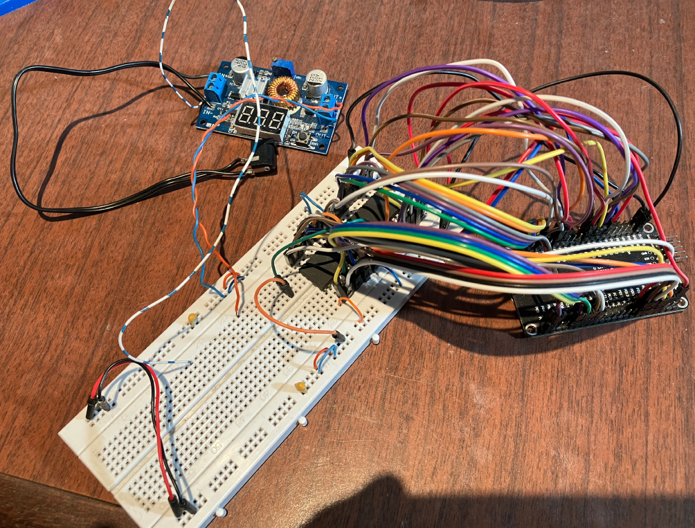
- You just wire some pins directly from an stm32f407 board to the MX29F1615. I just put the chip on a breadboard and wired some jumpers up.
- You have some kind of switch that can switch between +5V and +10V to the _BYTE/VPP pin. Usually you leave it at +5V. I just used an adjustable LM2596 PSU with +12V in, and adjusted to produce +10V out. My ‘switch’ is the orange arduino jumper just below the chip on the breadboard.
- You plug the stm32f407 in over USB. It appears as a serial device. You open a serial terminal to talk to it.
- If you want to erase the chip, you enter the ‘e’ command and some prompts will tell you to put +10V on the _BYTE/VPP pin. The chip is seemingly erased quickly but I have tended to leave +10V connected for a few mins to allow for any background processes to complete. Then you switch _BYTE/VPP to +5V … and now for the weird thing, you cannot check that the chip is full of FFFF’s until you power cycle it , so generally I unplug the stm32f07 board and flash ROM and then power it up again.
- Writing to the chip is similar. You’ll need to manually move the _BYTE/VPP pin to +10V, and then upload what you want to ‘burn’ via xmodem. The writing process has no decent way to check if what its written has actually worked (because it can’t drop that _BYTE/VPP pin to +5V), but uploading 512K is pretty quick, and at the end you just wait a few minutes and just switch the _BYTE/VPP pin back to +5V, and power cycle the board and chip and then you can read back what you wrote. I have an md5 sum function in the programmer so it can read the 512K you wrote and spit out an md5 sum which you can compare with an md5sum you did on your PC. Everytime I’ve done this it works first go.
Some people might not like this jiggling with voltages, but I probably spent only about 2 hrs of my life getting this to work So that’s a good thing.
I’ll note too that I made the flash programmer pretty much specifically for burning for 68000 machines like the Amiga. Importantly you do not have to byte swap anything like you would with some generic programmer.
And so I could flash an MX29F1615 now. To test I just tried with a 3.1 image at the beginning of the ROM. So I tested this on my A500++. It has a 42 pin Kickstart socket. I could not be bothered reading up how it has pins 1 and 42 connected, so I just bent those pins of the MX29F1615 gently out at 45 degrees and soldered some wires to them which I then tied to GND somewhere nearby on the mainboard (ie. pins 2 to 41 are inserted into the Kickstart socket, but 1 and 42 are bent outwards and a GND wire soldered to both). I’ll note that pin 1 is A18, and pin 42 is A19, so different combinations of high and low with those two pins will give you access to four different 512K images. Tying both low gives us the ‘1st of the four’. That got me an A500++ booting Kickstart 3.1 off a floppy.
(I will note that after I made this DIY programmer, I discovered this Arduino Mega 2560 based MX29F1615 programmer that is a bit closer to what I’ve done).
Custom Kickstarts
Most howtos for ‘custom kickstarts’ will point you at the remus and romsplit tools . They are Amiga native tools (though you can obviously run them in an emulator as well). I looked at the requirements for those tools and thought ‘that’ll probably take me a while to get those requirements sorted’, so then I remembered amitools. I’d used them some time ago, but basically they are a bunch of python scripts that do all the remus/romsplit stuff but on your PC. Amongst amitools are some other interesting tools like rdbtool that I ended up using later as well. The amitools documentation is excellent too (I’ll just note that I originally ran the amitools straight from the bin directory in the git repo thinking I didn’t really need to ‘pip3 install’ it. I would say 99% of it works OK this way but I realised later it does not work 100% this way … so make sure you ‘pip3 install’ it).
Essentially you run romsplit on a Kickstart image (using 3.1 in the example here)
cd sometempdir
romtool split /tmp/amiga-os-310.rom  -o .
You then get a directory probably called something like “40.63(A500-2000)”. If you cd into that directory you will see all these device and library files (with extensions containing a version number).There is also a file called index.txt. Edit that file, remove the line with scsi.device on it and save. Now get the bootide.device and ide.device that you compiled earlier and copy them into the same directory that has all the library and device files. Now build the new ROM
romtool build -o /tmp/amiga-os-310-with-ide-device.rom -t kick -s 512 index.txt bootide.device ide.device
And now flash the amiga-os-310-with-ide-device.rom file to your MX29F1615 (So for me, I would ‘e’ erase it then ‘w 0’ to write to the first of the four 512K blocks).
The first time I booted this I had my CF card installed in my IDE interface. I had previously partitioned it using a different ide.device file, and the first partitions was an FFS one containing Workbench and the 2nd partition was a PFS3 one containing some WHDLoad stuff.
So my A500++ did autoboot!!! But it could only see the first partition. It could not see the PFS3 one … and then I started going round in circles trying to figure out why.
Troubleshooting
So this is where thing’s came a bit unstuck. So I could now auto boot off the first FFS partition containing Workbench 3.1. But the 2nd partition , a PFS3 one would not appear. Logically I started up HDToolbox to check out partitions etc, and I noticed if I tried to save anything from HDToolbox I would get an “Error 1 on write!” .. so it would never save. Worse was that after exiting HDToolbox, having failed to change anything there was a super high probability I would get some ‘read block errors’ just doing normal stuff on DH0:. Hmmm. Seemingly if I rebooted, all was fine again.
Then I tried lots of subtle modifications to the AIDE source code to try to get HDToolbox to work. The other (rkide?) ide.device I had been using from floppy did not have a problem saving from HDToolbox, and I could see the source code was very similar or based on the same origin code. I then tried to hack parts of the rkide driver into the AIDE one … but ultimately nothing worked. Initially I thought it might be because the AIDE driver is so much faster (the rkide one was doing 680KB/s in Sysinfo and the AIDE one consistently did more than 1MB/s). But attempts to slow it down both didn’t slow it down much nor fixed the problem. Then I started to think that the read/write sector stuff is actually OK, but its possibly some SCSI command that only HDToolbox sends that somehow ‘sends it off the rails until you reboot’.
Super weird. In the process of repeatedly making a modded AIDE ide.device, then reflashing the MX29F1615 … I ended up breaking a leg off (pin 1) which is super annoying. Fortunately I was able to ‘just’ solder a wire to what was left of the leg and get it going again (and also I had one spare MX29F1615). Ultimately if I never run HDToolbox, it all seemed to work fine. I’d resigned myself to avoiding running HDToolbox (I’ll note too that I also ended up getting a 74LS688 and could then map the IDE interface to 0xDA0000 like the original designs .. but I still had the same issues with HDToolbox).
Then I remembered something. If you poke around various Amiga forums you often come across posts of ‘My CF card doesn’t work’ and ‘My CF card works fine’. Ultimately not all CF cards behave the same, so I found an old 48MB (yes that small) CF card and tried that in the Amiga 500++.This time HDToolbox worked perfectly. So I still think there is some SCSI command that triggers some IDE activity which ‘works OK on the old 48MB card’, but ‘screws up on these generic 1GB cards I bought from some random auction site seller’.
So then, if you have one of these CF cards that hates HDToolbox, what do you do? The card works perfectly if I never run HDToolbox, but chances are that when you first set up the card you want to use HDToolbox.
I didn’t think FS-UAE could do what I wanted, so then I had a look at rdbtool in amitools. It could do what I wanted. Essentially:
- connect the CF card to your PC. My linux setup is such that nothing ever automounts which is perfect here (I realise that’s not normal … and it’s up to the reader to figure out how to deal with that).
- Make a note of the device file used by the CF card (ie. cat /proc/partitions and look for a tiny one that is probably the last one in the list. HUGE warning here for people that have never done this before. YOU MUST GET THE DEVICE FILE RIGHT, otherwise you risk destroying the OS of your PC).
- In my case it was /dev/sde . I have a 1GB CF card, so it shows up with a number of blocks (990864) approximating that size ;
8 64 990864 sde - Then I just sudo to root because I am lazy. Otherwise chmod 666 the device file of the CF card , or chown it or whatever you need to do for your regular user to gain write access to the device file.
- Make sure you have installed amitools and rdbtool is in your path, and for me to init the CF card with a new RDB I did this (again, change the device file to whatever your CF card is showing up as in /proc/partitions)
rdbtool /dev/sde init
Doing the ‘init’ like that above worked fine on my 1GB card, but I repeated all these steps on the 48MB card I had … and due to a combination of its size and rdbtool assuming ‘one head’, I had to change the command to rdbtool /dev/sde init rdb_cyl=4
- Add a bootable FFS (FastFileSystem) partition as the first partition. The ide.device can autoboot fine off FFS, but it cannot autoboot from PFS3 (well I never could find a way).
rdbtool /dev/sde add size=127MiB name=DH0 bootable=true max_transfer=0x1fe00
- Now you could just go
rdbtool /dev/sde infoand maybe add a few more FFS partitions to the CF card. For example, adding DH1 as a 200MiB partition would be
rdbtool /dev/sde add size=200MiB name=DH1 max_transfer=0x1fe00
And once you’d done that you could put the CF card in the Amiga, boot off the the ‘1 of 6’ disk of Workbench 3.1 and you should see a DH0:NDOS and DH1:NDOS icon. You can then simply right click and format those, then proceed to install Workbench on to DH0:
But, I still wanted to put some PFS3 partitions on the CF card. ie. One smaller FFS partition at the start for Workbench, and one or more larger PFS3 partitions taking up the rest of the CF card.
- First get the pfs3aio file out of the aminet distribution for PFS3 and put it in your current directory
- Now add a PFS3 partition (I am assuming here that I did not add DH1 as an FFS partition as shown in an earlier example).The automount=false is super important.
rdbtool /dev/sde fsadd pfs3aio + add size=300MiB name=DH1 max_transfer=0x1fe00 automount=false - So at this point I have a DH0 as FFS, and DH1 as PFS3. Run the rdbtool info command and make a note of the settings for the DH1 partition. Here’s an example of what I noted down when I was doing this on the 48MB CF card
rdbtool /dev/sde info

....
Partition: #1 'DH1'    644   2951 73856 36Mi 78.29% PFS3/0x50465303
                                   blk_longs=128, sec/blk=1, surf=1, blk/trk=32
...
There are a few things to note down (as this will vary from CF card to CF card and from partition size to partition size). Note the 644 and 2951. The 644 is our LowCylinder and the 2951 is our HighCylinder. Also note the surfaces (surf=1) and the BlocksPerTrack (blk/trk=32).
- I put the CF card into the A500++ and booted off the ‘1 of 6’ floppy disk for Workbench 3.1 and saw the DH0:NDOS on the desktop. I formatted it by right clicking, and then just ran the ‘Installer’ and fed in the other 5 floppies (you can do this in fs-uae as well which is obviously faster).
- Now you need a floppy with that pfs3aio file on it (or if you boot the CF card in fs-uae you can copy that file directly to the hard drive). You need to put that file in the ‘L’ directory of DH0:.
- Now I boot the CF card in the A500++ again. For reference, DH0: is working fine, but DH1: is nowhere to be seen.
- You need to use a text editor to create a mountlist file. I created file DH0:devs/ide.ml and put this in it (this is based on my example for the 48MB card, not the 300MB example). The only lines I need to adjust are ‘the name’ (ie. DH1) and Surfaces, BlocksPerTrack and LowCyl and HighCyl.
DH1:
FileSystem = l:pfs3aio
Device = ide.device
Unit = 0
Flags = 0
Surfaces = 1
BlocksPerTrack = 32
Reserved =2
Interleave = 0
LowCyl = 644
HighCyl = 2951
Buffers = 30
GlobVec = -1
BufMemType = 1
DosType = 0x50465303
Mount = 1
#
- Now try to mount it
mount DH1: from devs:ide.ml - There was probably nothing printed at the CLI prompt after the mount command. That’s good. If you got a message about it already being mounted it’s highly likely you left off that automount=false option mentioned earlier. rdbtools has a ‘change’ command that let’s you fix that.
- Now run the CLI format command (I was hoping I would get an DH1:NDOS type icon on the desktop so I could format that way, but it never appeared)
dh0:system/format drive DH1: name DH1
- Now you should have an icon on the desktop for DH1. If you want DH1: to mount every time automatically you’ll need to add that mount command to the s:startup-sequence.
- Now you can copy files back and forth and it all works. However, I often find when I put the CF card back on my PC and access it via fs-uae that it doesn’t automount … or it sort of half automounts. Actually what I find is that I boot off the CF card inside fs-uae, then type that same mount command it says its already mounted. But if I try to access DH1:, it cannot do it. I am guessing here that some of the cylinder geometry that fs-uae decides is different to whatever rdbtool put in place. The workaround I have is to add a second entry to my ide.ml mountlist (with just the name and device changed)
UDH1:
FileSystem = l:pfs3aio
Device = uaehf.device
Unit = 0
Flags = 0
Surfaces = 1
BlocksPerTrack = 32
Reserved =2
Interleave = 0
LowCyl = 644
HighCyl = 2951
Buffers = 30
GlobVec = -1
BufMemType = 1
DosType = 0x50465303
Mount = 1
#
Now in fs-uae I can do this
mount udh1: from devs:ide.ml
and it should mount under the alias udh1: . It’s probably not a super correct solution as it is sorta still mounted as dh1: but the OS can’t access it as dh1: so its probably OK
The end result after all this effort is:
- I can autoboot an Amiga 500 off the IDE interface so long as its an FFS partition.
- I can have PFS3 partitions so long as they are mounted via a custom mountlist, and obviously are not the first partition.
- I can reliably use my cheap 1GB CF cards so long as I don’t use HDToolbox. If I was motivated I’d try some other cheap CF cards to see if I could find ones that do work OK with HDToolbox.