So I ended up buying an Oric Atmos motherboard on ebay.co.uk. I don’t have an Oric Atmos to repair. I somehow rationalised this as ‘this is cheaper than buying a whole Oric’. Of course a key problem with buying an Oric motherboard is ;
“There is no keyboard”
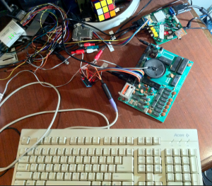
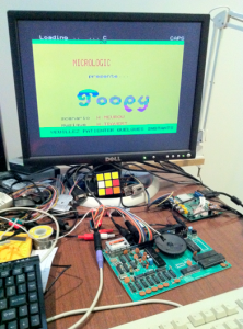
So for a few weeks the Oric motherboard sat on my desk. I could power it on. You just need a 12V DC supply (UPDATE: 20180402. You have to be quite careful with the choice of PSU here. As I found out later, some of my 12V adapters end up flooding the machine with 10V! instead of 5V due to the strange use of a 7905 to derive the power in the Oric. I think I will end up desoldering the 7905 and replace with a small DC-DC adapter). The RGB output can go straight into my Gonbes (I run the R, G an B signals through 1K resistors) and I could at least confirm that it started up and got to a BASIC prompt.
But how to do a keyboard? The Oric service manual is online somewhere, and shows it’s an 8×8 key matrix;
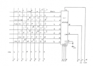
In the case of the Oric, a 4051 analog switch is ‘somewhere’ in the keyboard assembly, so there are 8 ‘column’ IO pins (IOA7 – 0) coming from the Oric motherboard, but then only 3 row select pins (PB2-0) and a sort of COMmon pin. Unlike systems where you have 8 outputs and 8 inputs for the key matrix, the Oric has 8 output columns, and the 8 rows are ‘inputs’ but only to the 4051. Which of those 8 rows is being read at a given moment is determined by the 3 binary output pins from the Oric. The COMmon pin is the one input pin from the keyboard.
So I could just get a lot of key switches and a 4051 and make my own keyboard.
However, I thought I’d have a go at getting an Arduino Uno to ‘pretend’ how the keyboard works, and feed a PS2 keyboard in to it. So basically a PS2 to key matrix converter.
So there are a few PS2 keyboard libraries for the Arduino. I found one, then hacked it a lot so that it no longer attempted to convert to ASCII, as there was not much point. I was just interested in the raw key events. The other part is mimicking the key matrix. Effectively the Arduino now uses 8 input pins for the Oric’s 8 column outputs (IOA7 to IOA0). And then another 3 input pins on the Arduino to read the 3 binary outputs for the Oric rows (PB2 to PB0). Then there is the one output pin (COM). The idea I had was that you would watch the Oric scanning the columns and then watch it scanning the rows and send the one output pin (COM) low at the appropriate moments.
This sounds all fine, but there is a bit of guess work especially related to timing. This took me a fair while to get working properly and I ended up hooking up a logic analyser to see roughly what was going on in BASIC when scanning the keyboard. The basic deal is that the Oric will first send IOA7 low for about 500us, then IOA6 low for 500us and so on. During the 500us, PB0,1,2 initially start low, but then all go high and effectively count down from 7 to 0 over about 400us, with about 50us per ‘count’. I suspect the Oric only reads anything AFTER PB0,1,2 all go HIGH.
Here’s some logic analyser output of a keyboard scan.
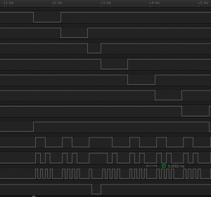
The top 8 traces are the IOA7 to IOA0 column lines. The next three are PB2 to PB0 that drive the 4051, and the final trace at the bottom is COM. In this example, COM goes low some time after column 5 (IOA5) goes LOW (the short pulse on the 3rd trace down). And if you look at the three traces just above COM, you’ll see they are HIGH, HIGH, LOW, so PB2 to PB0 = 110 or ‘6’ in decimal. If we go back to the Oric schematic of the keyboard, the intersection of column ‘5’ and row ‘6’ is the ‘A’ key, so this is an example of someone pressing ‘A’. If you look more closely, you’ll see that after IOA5 goes LOW, there is a short pause, and then PB2 to PB0 all go HIGH (kind of like setting PB2-0 to ‘111’ or ‘7’). Then the key scanning code decrements PB2-0 to ‘6’ or ‘110’. It’s then that COM is sensed LOW.
Anyway, I have hacked together some ‘mostly working’ Arduino IDE code that waits for a PS2 keypress and then mimicks pulling COM low at the appropriate moment. Sadly it is not 100% successful. It works perfectly in BASIC and many games, but in several games, different key scanning code is used, that is a lot more optimised … and well I cannot detect the row and column address quick enough, so the key event is lost. Think of it this way. Once a key is pressed, the Arduino monitors the IOA7-0 and PB2-0 lines to see the correct set of values for a key (like the example for pressing ‘A’). Once the code see’s the right combination, it sends COM low. At the moment, after optimising the code a fair bit, I can take up to 4 or 5 microseconds from ‘detecting the correct row/column’ and then sending COM low. That is fine for the key scanning code used in BASIC, but in a few games they must output the IOA7-0 and PB2-0 values and check COM very quickly (ie. in less than 4 or 5 microseconds). That’s something I need to work on.
The basic wiring detail is below. This is the pinout of the 14 pin connector on the Oric (p14 is the end closest to the RF modulator), and what pins on the Arduino they go to (it might be worth double checking this pinout, as I thought I read that there might be some variations of it);
14. +5V – Arduino Vcc
13. COM – Arduino D2
12. IOA4 – Arduino D12
11. IOA5 – Arduino D5
10. GND – Arduino GND
9. IOA6 – Arduino D6
8. PB0 – Arduino A0
7. PB1 – Arduino A1
6. PB2 – Arduino A2
5. IOA7 – Arduino D7
4. IOA3 – Arduino D11
3. IOA2 – Arduino D10
2. IOA1 – Arduino D9
1. IOA0 – Arduino D8
For the Arduino to PS2 connector;
PS2 CLK – Arduino D3
PS2 DATA – Arduino D4
PS2 GND – Arduino GND
PS2 VCC – Arduino VCC
Here’s the code;
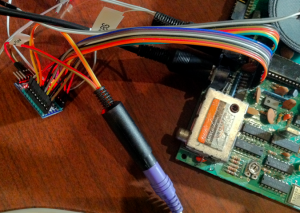
Here it is all hooked up. I originally used an Arduino Uno, but I now have a Arduino Mini hooked up to make it a little tidier. I have the RGB going into my Gonbes.