So I succumbed again, and bought a Commodore 128 off the local auction site. It was very yellow, advertised as ‘untested’, but came with a power supply. I bought it more for curiosity. I know most C128’s were simply used as C64s … and well .. I already have a C64C.
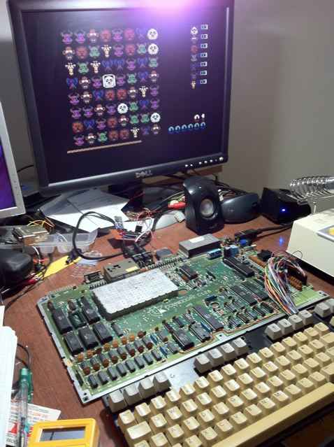
Anyway, when I got the C128 home, I checked the voltages from the PSU. They looked good. A C128 PSU has the same square plug as an Amiga PSU, but only the GND and +5V pins are the same between the two. Just like a C64, the C128 has a 9VAC feed into it. So the PSU seemed OK. I powered it up and got the following;
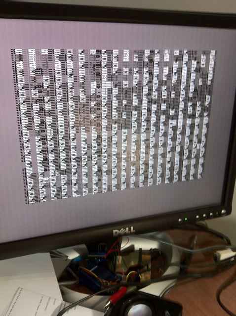
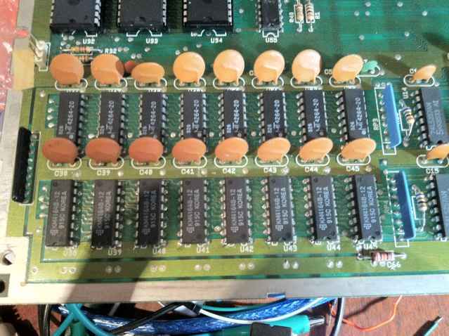
Yep, garbage (NB: I for whatever reasons only had the luminance hooked up to the svideo input of my monitor, hence the black and white output). Often you buy things ‘untested’ hoping that it ‘just works’, but this one did not. This then turned into a troubleshooting exercise to try to find out what was wrong. The fact that it had a picture at all and was in sync was a reasonably positive sign. I thought ‘maybe RAM’, so found some articles suggesting checking the temperature of all the DRAMs (my C128 has 16 x 4164s to make up the 128KB). I did not have any clever thermal temperature thing so just put my finger on each chip in turn looking for a warmer one. They all seemed ‘not that warm’, and none were any warmer than others.
I tried reseating chips. Compared to the C64C there are quite a lot of socketed chips. No, still broken.
Then I found various notes on piggybacking a 4164 on top of each 4164 to see if it boots up. Supposedly the piggybacked chip (which is not soldered in) will function in place of a broken DRAM. Nope. Still would not show more than garbage.
Then I came across the C128 service manual. It has a lot of step by step processes to try to narrow down where a fault is. It actually assumes you are booting from some sort of test cartridge (which I did not have), but I thought it might point me in the right direction.
So I worked through that guide. It starts by getting you to check various clocks. I don’t have a scope, but my logic analyser can measure fast enough to confirm various clocks. So my C128 seemed to be producing various clocks OK. I had some variations which I assumed might be related to the lack of a diag cartridge. For example, the 2MHz output of the VIC II was closer to 1MHz than 2MHz. And the clock to the Z80 is a strange 2 pulses then a gap, then 2 pulses then a gap … which I think is normal.
So it kinda looked good so far. Then I got to the DRAM checking section of the manual. Again, I got pulses where there should be pulses. Even the databus checks showed data on all the chips …. but that is probably reasonably inconclusive.
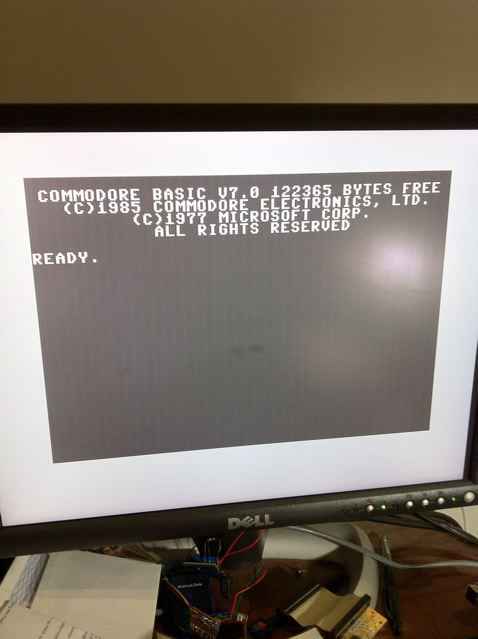
Then the manual suggested lifting up one end of the CAS* resistors (R29 and R30) and sort of swap them around. ie. So normally R30 would drive CAS* on the upper bank, and R29 the lower bank. By lifting them up and then running two short wire wrap wires appropriately, R30 now drove the lower bank, and R29 the upper bank. I turned it on, and behold it seemed to work (I still only had luminance connected).
Now, I am a C128 newbie here, but it sounds like the lower 64K bank is primarily used even in C128 mode. So the lower bank HAS TO WORK. Obviously mine was a bit broken. I put the CAS* lines back the way they were, and it went back to the garbage on boot. Then I retried the piggyback technique for the 4164s in the lower bank … but still no go.
I then thought I could waste more time trying to figure out which is the broken DRAM(s) in the lower bank or simply replace all of them. So I decided to replace all of them.
Now, I have attempted desoldering enough times to know I do not have the right tools for desoldering, and would probably mess up the circuit board. However, a few months back I experimented with using a regular paint stripper for desoldering. Before you go off and attempt this because you ‘read that some other dude on the internet did it’, I’d highly recommend that you do not do it. While I find using a paint stripper very effective (the parts often just fall out), it produces way too much heat, and it’s very difficult to isolate the concentration of heat to a specific area … and you end up with a lot of other exceedingly warm components. I find the entire circuit board and chips are too hot to touch for close to 10 minutes after desoldering this way. Yes, alarm bells should go off re that alone. Up to now I had only attempted it on old boards that I did not care about … but given that the C128 was not working I took a very ‘what do I have to lose’ approach. And it seemed like fun.
This time I wrapped the bottom of the board with aluminium foil, only exposing the section around the lower bank (this is to try to reflect some of the excess heat).
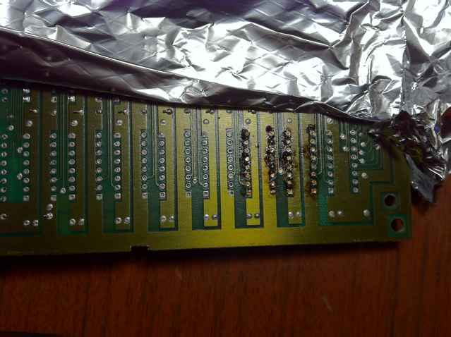
Then I went and desoldered all eight chips in the lower bank. Then did the tedious process of clearing each pin hole out and replaced the eight chips. The old parts were 200ns parts (and I could tell there had been earlier attempts to replace two of the DRAMs). I only had 120ns DRAMs. So I got them soldered in and powered it up with the CAS* lines back to normal. It powered on (ie. I had not melted the board).
So it seemed to work. It would boot up in C128 mode. It could switch to C64 mode. I could run some games in C64 mode. I tried to find a memory test program for the C128 but failed to find such a thing. I then got a C64 memory test program. In C64 mode it said the RAM was OK (obviously it is only testing the lower bank). While scratching my head about how to test the other bank, I decided to just swap the CAS* lines again, thinking I would then use the same C64 memory test program again.
So as per my earlier experiment it booted fine in C128 mode. But when I entered C64 mode I got an ‘OUT OF MEMORY ERROR IN 0’ error … which usually means your DRAM is broken a bit. Interestingly you could still type commands. I tried POKEing and PEEKing to get more info about the memory fault, but didn’t get far. I think the thing is that in C128 mode it does not test memory at all on boot, but it does in C64 mode. So I guess I wasn’t sure whether my paint stripper attempt had broken a DRAM in the upper bank … or whether it was like that all along (since I had never tested C64 mode prior to desoldering the entire lower bank).
This time I tried the piggyback technique again … and amazingly, C64 mode started perfectly when I piggybacked U52. More desoldering ensued. Originally I thought I would try snipping the legs of the faulty DRAM and removing it that way, but I could not get my sidecutters in close enough to cut the pins … so out with the paint stripper again, removed U52 and replaced it with a working 4164. I had actually now worked out which of the chips I removed earlier were still functional and used one of those.
Booted it up with the CAS lines still swapped. It booted OK in C64 mode. Tried the memory test program I had found. It said all OK. I’ve tried a few games now too. All looks pretty good. I still haven’t tried CPM mode though.