So, I have a SIO2Arduino setup hooked up to my Atari 800XL as a virtual floppy drive image thingee. It works pretty well and was really easy to make; one Arduino Uno plus one Arduino SD card adapter plus a few wires. Another popular one is SIO2SD. You can buy prebuilt SIO2SDs from Lotharek , but like a lot of these devices its ‘just a microcontroller hooked up to an SD card with some buttons, LEDs and maybe a screen. Currently SIO2SD is based on an Atmega32 microcontroller. I had a spare Atmega1284p (like I used in my SD2IEC). It’s a 40 pin AVR chip like the Atmega32 …. so I set off to convert the SIO2SD software to run on the Atmega1284p. However, when I finished I thought I’d see if it would compile for an Atmega328p (as is used in the Arduino Uno). And hey it did compile.
So I’ve concentrated on getting it all going on the Atmega328p. It’s compiled as a native AVR program (ie. not Arduino IDE based), so you’ll need to use an ISP programmer to ‘burn it’ in (I just use another Arduino Uno with the ArduinoISP sketch)
Anyway …
The latest versions of SIO2SD aren’t exactly completely open source (well I couldn’t find it). Currently (2016) the latest release is 3.1RC2. You can download the binary file of this to flash to your Atmega32. There is a version of SIO2SD with source, but this is v2.5.
I decided to download 2.5 and see if I could port it. I initially tried to compile it (for an Atmega32) and there are immediately some challenges;
- it was written for an older avrgcc.
- There are some subcomponents that were written in 6502 assembly, requiring an assembler called ‘mads’, which is written in ‘free pascal’.
Using a newer avrgcc (ie. make sio2sd.hex) gives errors like
interface.h:40:39: error: unknown type name 'prog_char'
 void interface_cfg_option_value(const prog_char *option,const prog_char *value);
Initially you add this to the Makefile to workaround this
AVRCFLAGS += -Wno-deprecated-declarations -D__PROG_TYPES_COMPAT__
But then you get errors like;
setup.c:49:20: error: variable 'ctval' must be const in order to be put into read-only section by means of '__attribute__((progmem))'
 static const char* ctval[] __attribute__ ((progmem)) = {ctval0,ctval1,ctval2,ctval3,ctval4};
More googling and you find you need to change all these lines to include a 2nd ‘const’;
static const char* const ctval[] __attribute__ ((progmem)) = {ctval0,ctval1,ctval2,ctval3,ctval4};
Then you get all these xex related errors, that relate to the unassembled ‘mads’ components. I attempted to compile the mads source using a recent Free Pascal. That failed. Then I noticed the ‘mads’ distribution came with a Windows exe of ‘mads’, so I spun up a Windows VM, ran mads
mads -o:xex_loader.bin xex_loader.asm

mads -o:sio2sd.xex sio2sd.asm
And copied the assembled files back to my linux box in the appropriate sub directories of the sio2sd source (the sio2sd.xex goes to the atari_conf_tool dir)
So that got my ‘make sio2sd.hex’ to succeed … for an Atmega32.
So I changed the MCU setting in the Makefile to
MCU = atmega328p
And tried to compile again (rm *.o ; make sio2sd.hex)
And now comes the search/replace saga of trying to adjust Atmega32 registers and bit settings to match a Atmega328p. Its not too bad … but it took a while. Atmel have a migration doc for going from Atmega16/32 to Atmega164p/328p/644p. I originally used this doc when porting the code to the 1284p (since a 644p is pretty close to a 1284p). Of course the doc is also for porting to the 328p.
Some of its a bit more complicated. sio2sd uses a series of DELAY macros in delay.h that ended up changed to look like
#define DELAY_START(cnt) { \
        TCCR1B = 0;     \
        TCCR1A = 0;     \
        TCNT1 = 0; \
        OCR1A = cnt; \
        TIMSK1 = 0; \
        TIFR2 &= 0xfc; \
        TIFR1 |= 0x27; \
        TIFR0 &= 0xfc; \
        TCCR1B = 3;     \
}

#define DELAY_REFRESH TCNT1=0;
#define DELAY_IN_PROGRESS bit_is_clear(TIFR1,OCF1A)
Fixed that, then next bunch of problems to do with uart configuration in sio.c. I initially missed a few bits and had to return to this later. Here’s my final diff
diff sio.c ../../tmp/sio2sd-code/sio.c
339,340c339,340
<     while (bit_is_clear(UCSR0A,UDRE0)) {}
<     UDR0 = c;
---
>     while (bit_is_clear(UCSRA,UDRE)) {}
>     UDR = c;
362c362
<     while (bit_is_clear(UCSR0A,RXC0)) {
---
>     while (bit_is_clear(UCSRA,RXC)) {
367,368c367,368
<     resp = UDR0;
<     if (bit_is_set(UCSR0A,FE0)) {
---
>     resp = UDR;
>     if (bit_is_set(UCSRA,FE)) {
371c371
<     if (bit_is_set(UCSR0A,DOR0)) {
---
>     if (bit_is_set(UCSRA,DOR)) {
1057,1058c1057,1058
<     UBRR0H = 0;
<     UBRR0L = NORMAL_SPEED_DIVISOR; // (XTAL_CPU/NORMALSPEED)/16-1;
---
>     UBRRH = 0;
>     UBRRL = NORMAL_SPEED_DIVISOR; // (XTAL_CPU/NORMALSPEED)/16-1;
1063,1064c1063,1064
<     UBRR0H = 0;
<     UBRR0L = HIGH_SPEED_DIVISOR; // (XTAL_CPU/HIGHSPEED)/16-1;
---
>     UBRRH = 0;
>     UBRRL = HIGH_SPEED_DIVISOR; // (XTAL_CPU/HIGHSPEED)/16-1;
1076,1079c1076,1078
<     UCSR0A = 0x00;    // UX2 (double speed (/8) on = 0x02 ; normal (/16))
<     UCSR0B = 0x18;    //TXE + RXE
< //    UCSR0C = 0x86;    //UCSRCSEL (0x80) + USBS (0x08) + (UCSZ1+UCSZ0) (0x06 = 8bit)
<     UCSR0C = 0x06;    //UCSRCSEL (0x80) + USBS =0(0x08) + (UCSZ1+UCSZ0) (0x06 = 8bit)
---
>     UCSRA = 0x00;    // UX2 (double speed (/8) on = 0x02 ; normal (/16))
>     UCSRB = 0x18;    //TXE + RXE
>     UCSRC = 0x86;    //UCSRCSEL (0x80) + USBS (0x08) + (UCSZ1+UCSZ0) (0x06 = 8bit)
1121,1122c1120,1121
<     UCSR0B = 0x08;    //restart uart
<     UCSR0B = 0x18;
---
>     UCSRB = 0x08;    //restart uart
>     UCSRB = 0x18;
And that is actually enough to get it to compile … but it didnt work.
Actually, initially the status LEDs never worked, then it twigged that I needed to disable the fuse that was enabling JTAG (as the JTAG pins are shared with the LED GPIOs). Eventually my avrdude line was this (the fuse settings for the atmega1284p are actually the same).
avrdude -P /dev/ttyUSB0 -b 19200 -c avrisp -p atmega328p \
 -U flash:w:sio2sd.hex -U lfuse:w:0xef:m -U hfuse:w:0xd9:m
So I had LEDs that could light up a bit, and I had an LCD display that spat out ‘card init error’. Lots of debugging later, lots of research on how to talk to an SD card, and lots of changes to mmc.c and it seems to work a bit (still a bit nervous as there are lots of changes to mmc.c). Basically
- Lots of changes to mmc_card_init since I have a modern SDHC card and I could not get it to initialise properly with the old code. I now send a CMD0, lots of 0xFF’s, a CMD8, a CMD55, an ACMD41 with HCS set, then a CMD16 to set 512 byte blocks (but that may not be required) (the 3.0+ releases of SIO2SD also note that there are lots of changes to avoid card init errors)
- Changes to the sector read/write/erase functions. Originally these take a sector address and convert it a byte address, but in HCS mode you use sector addresses anyway. So no need to convert.
So with my hacks to mmc.c I doubt it will work with older MMC cards now.
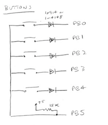
When I had this working on the Atmega1284p I could wire it up the same as the real SIO2SD, as they are both using 40 pin AVR chips. Of course the 328p has only 28 pins … and well there is not quite enough pins to do it the same. I ended up changing the 5 keys, such that instead of consuming five GPIO pins to read them, I basically have a 5×1 keyboard matrix. I have 5 strobes and one ‘read’ column. Four of the 5 strobes are the 4 data lines going to the LCD screen (so they have a 2nd job), so I just need one more output line (PB4), and one input line (PB5). The PB4 one is the ‘shift’ key in SIO2SD. The others are SW1 to SW4.
The keys.c file has a keymatrix scanning routine now. This seemingly small modification took me ages to get right. For days I could not get the keyboard to read at all, or it was very flakey. Eventually I worked out that when you drive one of the 5 strobe lines low, you need to ‘wait a bit’ before reading the one input line. It only has to be a microsecond or so, but you do need to wait a bit.
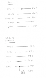
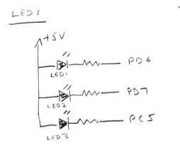
The other wiring lists look like those below. The SIO2SD site has p10 of the SIO connector supply +5V. I haven’t actually tried that as I have a wire soldered into my Atari connected to +5. SIO2SD also has a GPIO (should be PC4) connected to GND of the SD card. I just connect it via a resistor to GND instead. The LED resistors I just used 270 ohm resistors. The diode to PD1 is just a 1N4148.
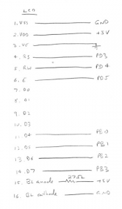
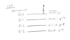
And the LCD wiring, and how I wire my Arduino Uno in as an ISP
I’ve also modded the code so I can use a 16MHz crystal instead of the 14.318MHz. I do have a 14.318MHz crystal, but I thought it might be more useful running it with a 16MHz crystal.
Using it
As per the SIO2SD site, you need a FAT formatted SD card with an ATARI folder in the root of it. You then put ATR and XEX images into this folder.
When you power on for the first time, you probably want to get to ‘setup’ mode. You hold down sw4 (PB3) while powering on. There are sort of two setup/config things … which is somewhat confusing. One is ‘setup’, the other is the ‘cfg tool’.
The ‘setup’ one is when the LCD display says ‘SIO2SD setup’ and you get to configure some general settings of the hardware. If you are having trouble getting it in to setup mode, try moving your SD card to a PC, delete the SIO2SD.CFG file from the root of your SD card, then pop it back in the SIO2SD and power it on. It should go straight to this ‘setup’ mode. You can use the buttons to select what the LEDs do, and how fast the SIO bus is, etc.
The ‘cfg tool’ is the typical ‘native Atari menu-ing program for selecting disk images’. You have two choices. One is pre-assembled with the v2.5 source; pajero_sio2sd.xex. The other you assembled with mads earlier; sio2sd.xex. When you did a ‘make sio2sd.hex’ it compiled in one of them. The magic that decides which one is used is in the main Makefile;
AVRCFLAGS += -DUSE_PAJERO_CFG_TOOL
So if ‘USE_PAJERO_CFG_TOOL’ is set it links in pajero_sio2sd.xex. If you comment out that line in the Makefile, it will pick the sio2sd.hex one instead. I currently am using sio2sd.xex as it seemed a little more stable … but I’m honestly not sure.
During ‘setup’ you get to define when this ‘cfg tool’ boots. The options are;
- never
- startup+shift
- every startup
- D1 is off – When D1 is not assigned
- shift pressed
I assume the last option is so that you can load the virtual disk from inside some other program (ie. not at boot time). I just use the startup+shift option (this is the ‘shift’ button on the SIO2SD; sw5). In fact I have changed the default in the code from ‘never’ to ‘startup+shift’.
So it does seem to work OK, but occasionally I see it do something weird which looks like its having trouble talking to the SD card … but is hard to tell.
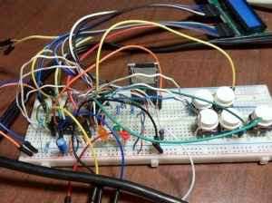
Below is my initial breadboard setup. You’ll notice I have an electrolytic across +5 and GND. I was thinking the SD card access was sucking quite a bit of power in certain cases … and I was trying to stabilise the supply. You need some 0.1uF decoupling caps regardless.
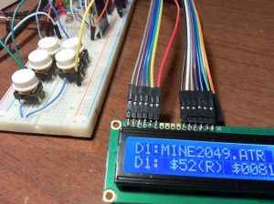
Below is the SIO2SD set up on a proto board. I have a much larger 1000uF electrolytic this time. It seems to work pretty well running from the PCB.
The basic deal with the LCD UI is
- sw2 (PB1) steps through the list of files
- sw4 (PB3) is like an ENTER key to select a file to load into a virtual disk, or if it’s a directory, it effectively ‘cd’s’ into the directory.
- The other keys do other stuff ;-). Check the sio2sd site for more info.
- Once you have a disk ‘loaded’, just power on/off (and probably hold the OPTION key on your atari)
The alternative is to hold down sw5 (PB4) when you turn on your Atari. Assuming you have ‘startup+shift’ set, it should boot into the sio2sd.xex. Pressing HELP will give you some brief info. Usually I am holding down the OPTION key when I hit ‘x’ to reboot out of sio2sd.xex.
And here’s the modded code.