A few years back I finally acquired an Acorn A3000. Like most A3000’s it did not work due to battery damage. I hacked away at it and eventually got it to work. My fixes weren’t exactly pretty, but I got it going and out of all the 80s home computers I have, I think the A3000 is pretty cool. Some time after that, several broken A3000’s came up for sale on my local auction site. I vaguely remember there being six. Someone else bought the ‘best three’ and for whatever reasons I decided to bid on the remaining three. ie. the worst ones. I won the auction.
Of course I did not need another three Acorn A3000s, but that first one was quite challenging to fix, and I love challenges so ‘why not?’.
When the three turned up I immediately pulled them apart and removed the remains of the battery. The battery damage seemed to vary a bit between the three that I had. Of the A3000’s I have, the first one had a very dark green mask for the mainboard. Of the three other ones, one had the dark green mask and two with a lighter green mask. The lighter green mask ones looked a lot worse. After removing the old batteries I tried using lemon juice, then vinegar to try to get rid of a lot of the green gunge. It cleaned it up a fair bit, but I could never get it to look as pristine as what you see on other people’s sites.
Rather than start on the dark green mask one, I picked one of the lighter green mask ones to start fixing. Rather than build a daughter board (like I did in that very first A3000) I thought I would at least first attempt to fix it with the chips in the board. I was probably asking for trouble with this approach. After a while searching and finding broken traces I still had not been able to get it to power on … so I gave up and shelved the project for a while.
Fast forward a year or two, and my day job has been super busy and I was after a good distraction. So I pulled out these A3000’s again. Rather than start with the lighter green mask ones. I thought I would start on the dark green mask one. After a few nights staring at circuit diagrams and checking traces, it started up and said ‘keyboard not present’. That’s a hugely positive sign. I fixed that and had another working A3000.
I moved on to the lighter green board that I had previously given up on. I had already put a lot of wires to fix broken traces but the board showed no sign of life. But then I noticed a scratch on the top surface of the PCB near the DRAM chips (ie. a fair way away from the battery damage). This scratch was over a trace that connected one of the data lines to the DRAMs. I repaired the trace and this A3000 also booted up.
Then finally on to the last one. When I pulled it out I realised I had started work on this one too and completely forgotten about it. I’d already removed the 74LS145s and RTC chip and resocketed ROM 3. This board turned out to be the hard one. The battery damage had spread further into where the ROM sockets are. Generally only a few traces on the ROM chips get damaged, but this one had oodles of traces damaged. I ended up having to resocket ROM 4 as well since the corrosive liquid had eaten away at the legs of the socket in some places. But it too eventually turned on and is fully working.
I’ll include photos below, but to generalise my repairs
- The RTC chip always seems to die. Desolder it, socket it and get a new one.
- The 74LS145’s are generally OK so far as the chips themselves are concerned. But check the continuity of all pins to and from the 74LS145s.
- Some traces around the top of the ROM chips often fail (eg. pins 1, 2, 32, 31)
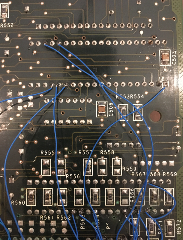
- The C(0) and C(1) traces between the IOC and the RTC chip often fail. If you find R551 and R552 underneath the board, often running a wire from them to the RTC chip fixes the broken traces
- Check all the continuity around the RTC chip.
- Often the traces between the 74LS145s and SK7 (the membrane socket closest to the 74LS145s) fail.
- Often the trace from pin 10 of IC4 (left most 74LS145) gets disconnected to its path back to pin 1 of the 8051. This is Id(0), which is effectively the ‘keyboard is present’ sense pin.
- The traces to the mouse socket pretty much always fail. I found that ‘generally’ the traces between the mouse socket and the ‘L’ links that are around the battery (L7, L8 , L9 …etc) often work, but between the 8051 and those L links fails. Hence I ran wires underneath the board between the 8051 and where those L links sit.
- Check the pullups are all connected to the 8051 on it’s P0(0) to P0(7) pins.
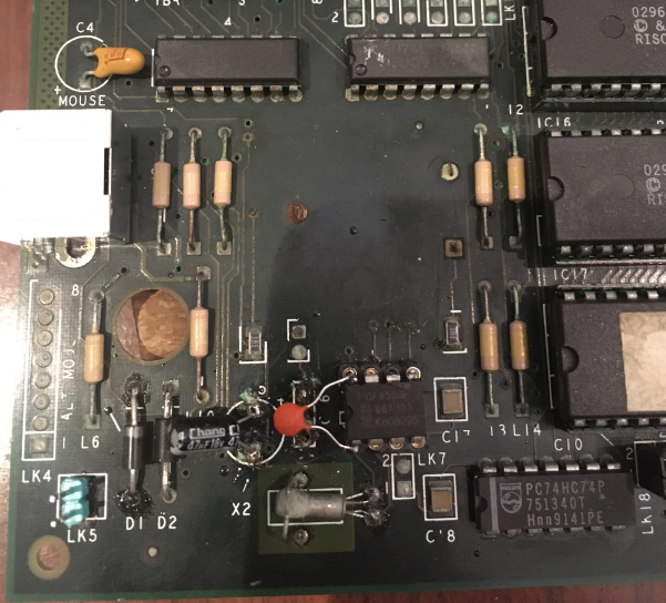
- Check the trace between pin 5 of the 74HC74 (down near the RTC chip) and pin 18 of the 8051
- Check the traces around the 74HC74 flipflop that’s in use (ie. pin 1 and 4 tied high, and pin 2 and 6 tied together
- I desoldered the mouse socket and replaced it on every single A3000. Often the old one is full of green gunge.
- My battery setup is a two AAA battery holder feeding into the two pins in the bottom left corner of the board and then installing the extra diode (I just used 1N4002) to feed in
- I ended up trying to clean the SK6 and SK7 contacts as best I could (though they were still a bit green) and at the same time cutting small bits off the end of the membrane connectors to get the keyboard working. Generally unplugging and plugging the membrane connectors makes them worse, so once its working don’t touch it. I should replace SK6 and SK7. I have read some recent references for places that sell them and that would increase the chance of everything lasting longer
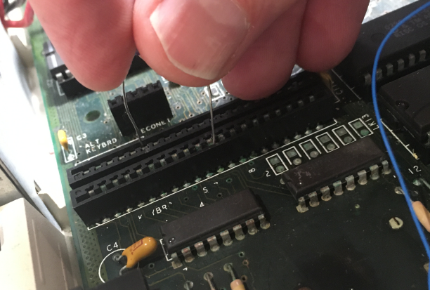
- It’s a good idea to work out the pins on SK6 and SK7 for pressing DEL on boot without the keyboard membrane connected. I have a photo below of putting a low value resistor (eg. 100 ohm) across the pins while powering on. That will save you wrecking the membrane connectors
- Check that pins that have a pullup are still connected to their pullup resistor.
When I am testing I am generally powering on while pressing DEL (or have the SK6 and SK7 pins shorted to pretend to press DEL), and the black and white composite output going to a monitor. Unlike a lot of other computers the RGB output won’t appear to work until you do some F12 wizardry to tell it what type of monitor and sync setup you have. Also note the LK24 and LK25 jumpers inside that control whether you have a composite sync monitor connected or separate H and Vsync
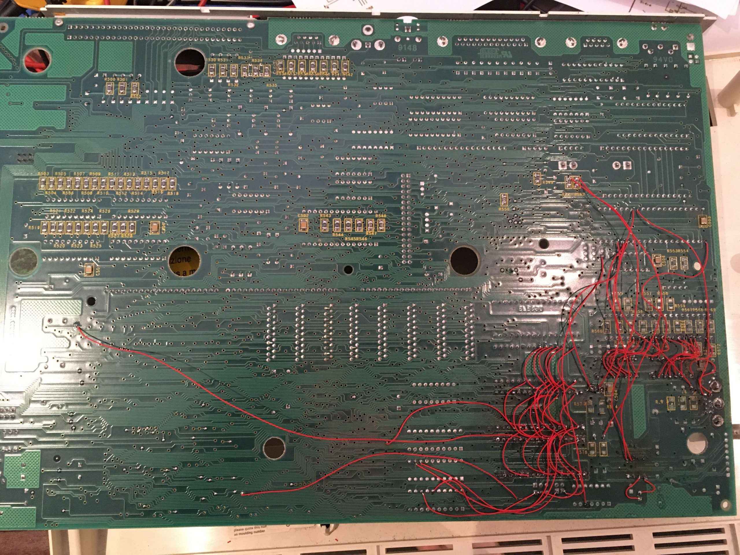
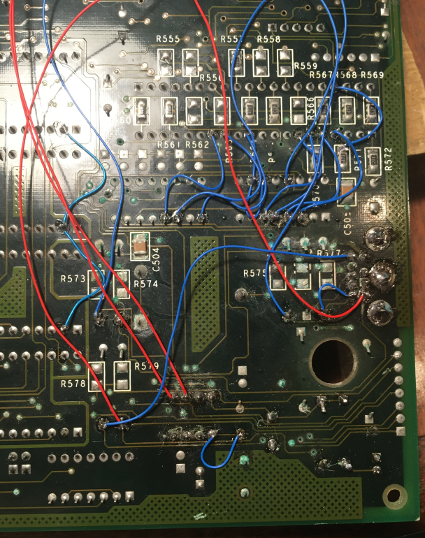
Here are the fixes on the first dark green board
Here’s that trick I mentioned earlier re pretending to press DEL without the keyboard membranes connected. I just used a 100 ohm resistor. You have to make sure you don’t actually push the pins in to the socket as it will wreck the socket pins. A resistor leg is much thicker than the membrane cables.
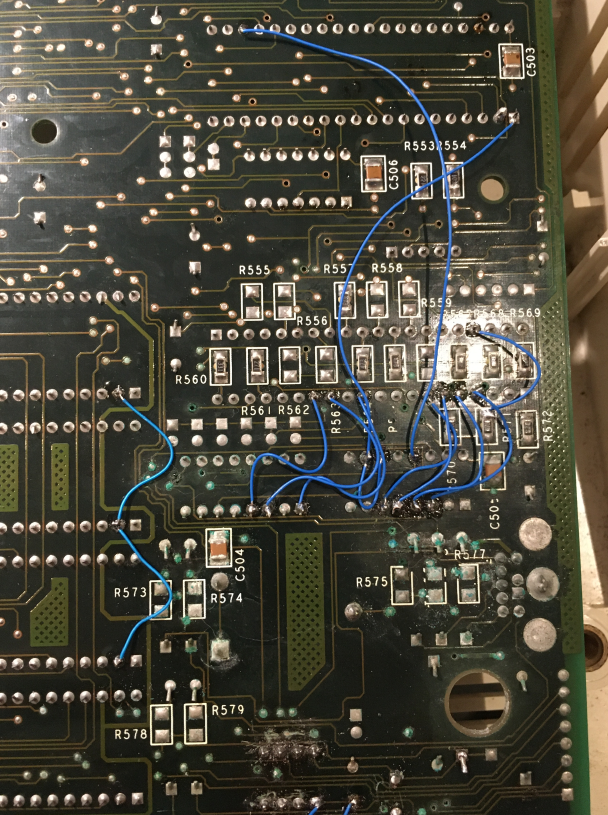
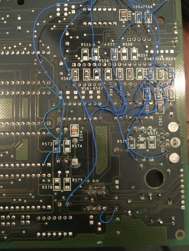
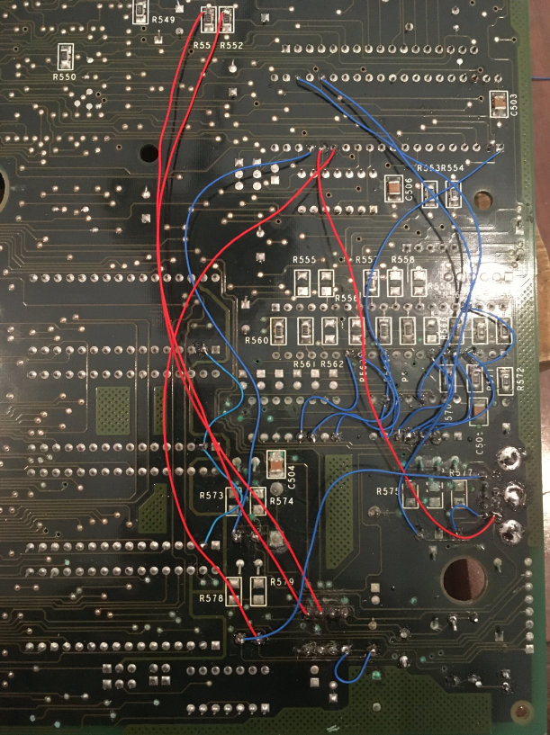
Here’s the next board
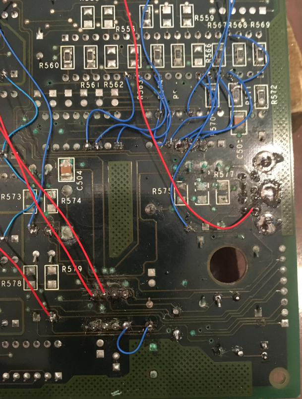
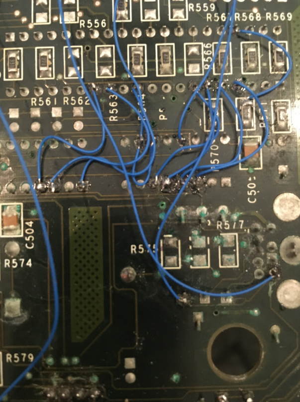
And I only have one photo of the last board. It was a lot of work!