The Acorn Archimedes A3000 came out in 1989. My vague recollection of the era is that the Amiga 500 was really popular around then, and even though the A3000 was a lot more powerful, it was in a price bracket that made it a lot more expensive. I probably didn’t know how much more powerful it was at the time as I had never seen one. Nowadays, machines like the A3000 have some historical significance since they had an early version of the ARM processors that power just about everything in the modern world.
So I was keen to get one. I already had a RiscPC, but that’s all a bit ‘modern’ in the greater scheme of things. The A3000 was earlier, and had an 8MHz ARM2 CPU, and about one MB of RAM. It had a similar ‘all in one’ form factor like an Amiga 500 with a floppy disk slot on the right hand side. A quick look at ebay.co.uk will highlight that A3000’s are horifically expensive if you can find one. I don’t think they sold in the same numbers that the Amiga 500 sold in, but the big problem with the A3000 is the battery for the real time clock.
If you go down the road of collecting old computers, you end up identifying two distinct classes; 1) the ones with no real time clock and consequently no battery on the motherboard and 2) Ones with a battery on the motherboard that has most likely leaked after 30 years. A lot of the early 8 bit computers had no real time clock so they will last forever ;-), but from the late 1980’s and definitely into the 1990’s motherboards often had a battery on board.
These batteries leak a very corrosive liquid and you end up with the ‘green gunge of death’ in one corner of a motherboard. In a lot of cases you have to bin the motherboard as the damage is usually pretty bad. In theory, the only systems from this ‘with real time clock’ class that will survive are the ones where an owner has bothered to remove the battery sometime before it started leaking.
Anyway …
I saw an A3000 on the local auction site a few months back. The seller highlighted that it had battery damage, that it only booted to ‘supervisor mode’ and said the ‘keyboard was not present’. It also had a broken case (not shown in the ad), and a working mouse. It did however have an internal IDE hard drive expansion (which I think are rare), and a memory expansion. The seller highlighted that the most useful thing in his auction was the mouse.
I bought it anyway.
Firstly the case was really badly damaged. It had broken plastic bits on the bottom part as well as a huge crack in the top like someone had stepped on it.
But the motherboard was in a pretty bad way. The battery had actually been removed, but obviously way after it had started to do damage. Unfortunately I don’t have a shot of the corner where the battery is prior to attempting my first repair. The empty part below is where the battery would be. If you look closely around that area you can see the green tinge of the battery corrosion
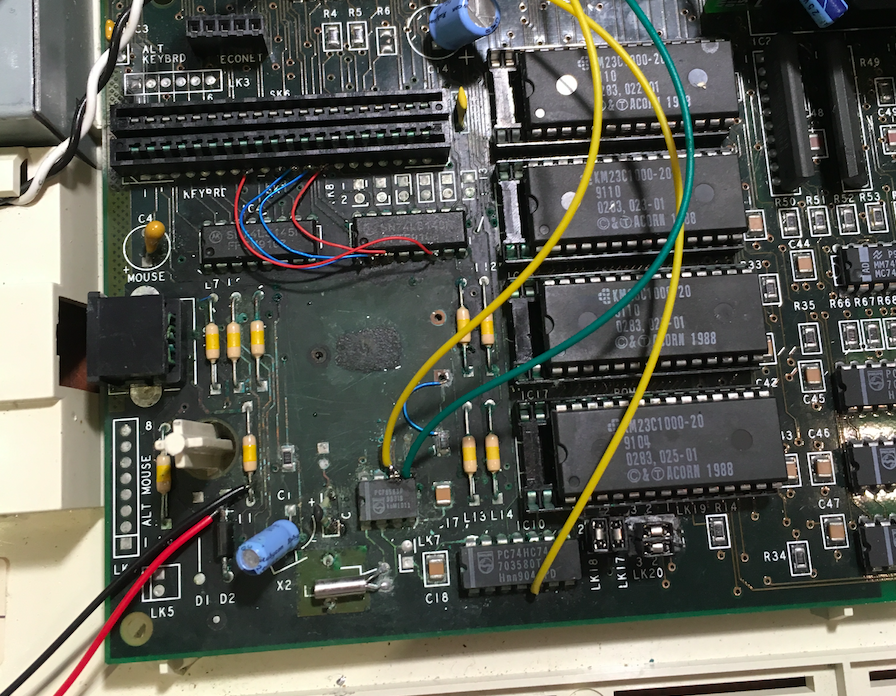
One of the problems with the battery location in the A3000 is its proximity to some pretty critical stuff;
- The keyboard connectors
- The mouse connector
- The two 74LS145’s that drive the keyboard matrix
- The PCF8583 RTC chip
- The ROM chips
In my case the green gunge was all around the two 74LS145’s near the SK6 and SK7 keyboard connectors, and the RTC chip. The lower keyboard socket SK7 had a bit of a green tinge already on the metallic contacts, whereas the upper one SK6 looked reasonably OK. Suffice to say the end of the keyboard membrane connector that went into SK7 did not look well. It looked like it was getting eaten away.
I tried cleaning up the area with a vinegar solution, but it was still a bit ‘green gunge-ish’
I ended up cutting a millimetre or two off the end of the affected membrane connector, but every time I booted I just got a supervisor prompt and a ‘no keyboard connected’ message.
I eventually worked out that a trace from pin5 of the 74HC74 (in the lower part of the picture) was not making it to the 8051 to drive its clock. Once I remedied that, it no longer told me that the keyboard was not connected. But only some keys worked, and holding Delete on boot (to reset the the CMOS RTC) did nothing.
Various attempts followed to trim more off the end of the dodgy membrane connector, but it seemed very intermittent and I still could not get a ‘hold down Delete on power up’ to do anything, so I ordered some 74LS145’s and replacement RTC chips and forgot about it for a while.
I then decided that since it was very hard to work on this small corner of the motherboard, that I would just reconstruct it all on a small daughter board (which would obviously be free of green gunge).
But before I did that, a key thing I wanted to do was to desolder the two 74LS145’s , the PCF8583 RTC chip and the two keyboard membrane sockets (SK6 and SK7). I have a small SMD hot air blower now, and the chips came out reasonably easily, but the two membrane sockets were very hard to remove. I tried multiple times before they came out. One of them had some bubbling on the plastic connector where it had gotten too hot, but they did eventually come out in one piece (As a side note, I’ve never seen anywhere that sells the membrane connectors as large as the SK6 /SK7 ones).
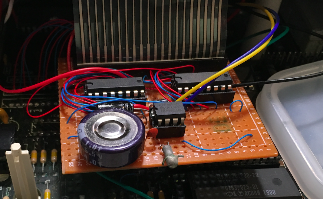
I used a small protoboard with SK6 and 7 at the top (you can only see one of the sockets in the photo). The two 74LS145’s below them and the RTC chip. I reused the crystal for the RTC, but instead of a battery, I decided to use a 1F 5.5V capacitor (pictured below). The 1F capacitor turned out to be a dumb idea as it barely held the config for a day. Instead, I ended up putting an AA cell in the unused battery compartment and wired it in through a diode. That seems to be lasting so far. The solution isn’t exactly elegant (the 2nd shot shows a piece of cardboard I use as an insulator).
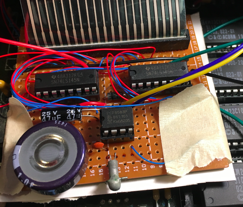
And from above;
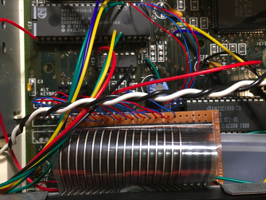
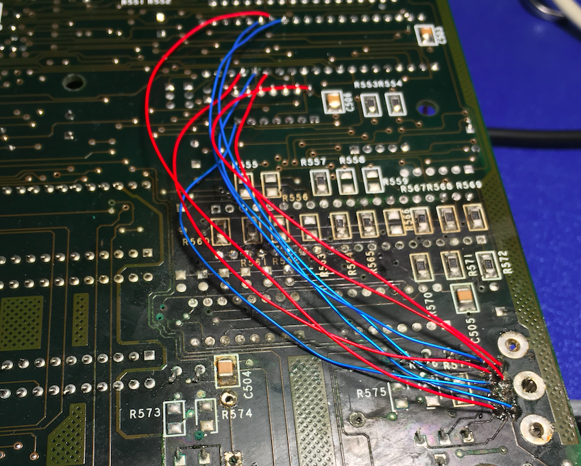
There are quite a few wires that run from the daughter board. A lot just went to SK6, and some others directly soldered to the 8051 and other chips, as I had a lot of damaged traces. The photo above actually shows some other hookup wires soldered to the 8051 for connecting an Amiga mouse via a DB9.
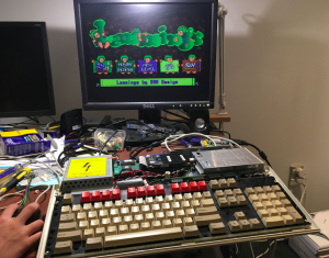
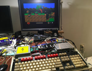
After a few attempts with this board setup, I was finally able to boot up with Delete key held down, and finally see a RISCOS Desktop! I’ll note here that I originally just used the black and white composite video out for testing. Later on I wired up the DB9 Analog RGB port into a DB15 VGA plug. I was hoping this might ‘just work’ on my Dell 2001FP, but it didn’t, and all the shots further on are the output going into my Gonbes and then into the 2001FP (NB: I actually did get it working with the 2001FP much later on, but it seems to work better via the Gonbes in RISCOS 2)
Initially I had no working mouse. The mouse socket seemed to be full of green gunge, and checking the continuity of a few of its pins showed only a couple of traces from it that actually worked. So (per the earlier photo), I ended up just soldering in a DB9 to the 8051 pins for the mouse, and running a two button Amiga mouse on it. That proved that I had a working mouse (though only with two buttons).
So at this point I was pretty excited. My very broken A3000 was now seemingly working. I had taken the IDE board out earlier, so put it in. It didn’t auto detect it on boot, but that’s just how RISCOS works. I had to follow some instructions here to configure it, and then I had a working 20MB hard drive!! It had Chuck Rock and a couple of other games on the hard drive and was working well. The memory expansion board also worked OK (increasing memory from 1MB to 2MB).
Next up I desoldered the mouse connector on the motherboard, and replaced with a non-green-gunge one. Most of the traces to the 8051 were damaged though, so I ran a series of wire wrap wires underneath;
With the modern optical mouse I was using on my RiscPC , I booted up and finally had everything working OK.
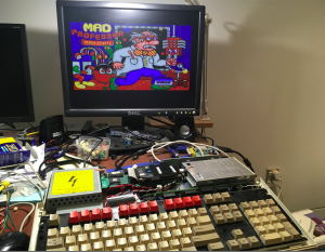
So far I’ve tested a few games, by writing ADF images directly to floppies on my RiscPC (using ImgToDisk). It all seems to work, though I can’t seem to get Chocks Away to work.
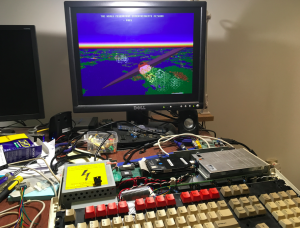
Now that I’ve had it for a while, it does put in persective just how much faster this thing was in 1989. An 8MHz CPU does not sound that fast, but one look at Star Fighter 3000 and you know this is quite a big leap over the Amiga’s of the time.
UPDATE: Just a note here about updating ROMs. My A3000 came with OS 2.x, and I wanted to try 3.11. I ended up getting AM29F040B flash ROMs, then realised that via the jumpers on the motherboard you cannot completely adjust the connections to use the AM29F040B. But you can ‘almost’ do it. I ended up bending out pin 1 of the flash ROMs so that they are not in the socket, soldered all the pin 1’s together and ran a wire to p15 of IC31 (for La<20>). Then you need to be creative with the LK17, LK18, LK19 and LK20 jumpers. Then I downloaded the riscos3_11.zip file. It conveniently has files IC24.rom, IC25.rom, IC26.rom and IC27.rom that I assumed corresponded to ROM1, ROM2, ROM3 and ROM4. This turned out to be completely wrong, as IC24.rom is actually the first 512KB of contiguous ROM memory space, and not the contents of the first ROM. What you actually need to do is concat IC24.rom, IC25.rom, IC26.rom and IC27.rom, then find some sort of de-interleaver program (or write one yourself) that puts the 1st byte of the concat in rom1.rom, the 2nd byte of the concat in rom2.rom, the 3rd byte of the concat in rom3.rom, the 4th in rom4.rom, and the 5th byte in rom1.rom and so on. And then it all works.