So in part 1 (Amstrad CPC ROM emulation using an STM32F4) the code I had for emulating a ROM (and some IO) with a cheap STM32F4 board for the Amstrad CPC 464 ran in a continuous polling loop. The code just watched _ROMEN and _IORQ going high and low, and acted appropriately. The (sort of cheating) way I was able to load a disk image from an SD card was to load the disk image during the Amstrad _RESET.
It bugged me that I was unable to interact with the STM32F4 SDIO interface after boot, as that would interrupt the polling loop. The main way of being able to use the SDIO interface would be to use interrupts for the _ROMEN and _IORQ lines, and then interact with the SDIO using the main thread of the program. I had discounted using interrupts for _ROMEN and _IORQ in the past, but I thought I would have another go at it.
The main reason I discounted interrupts is that in my experiments using interrupts, it would take around 120ns to get from an ‘edge’ (of say _ROMEN or _IORQ) to the first line of my interrupt handler. Then another 150ns or so before I get into the main part of an interrupt response routine (eg. For an interrupt on the negative edge of _ROMEN, my assembly code would be about 250 to 300ns after the negative edge before my code had read the Z80 address bus, done some sanity checks and pulled a byte to present as a ROM byte). The Amstrad is a bit more lenient than the Acorn Electron ROM emulator I had done before, in that a memory request (ie. a _ROMEN cycle) has _MREQ low for a minimum of about 360ns (the Amstrad’s memory cycles vary a bit).
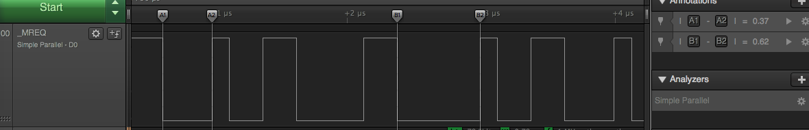
In the logic analyser output above you can see the _MREQ line from the Z80A. The two ‘lows’ with the time markers are ROM accesses. The shorter one on the left is about 370ns. The longer one towards the middle is 620ns. The shorter low periods you can see are the DRAM refresh cycles that the Z80 periodically does. They are about 250ns.
Anyway, I still thought 360ns would be a bit ‘tight’, so I thought I would try having the interrupt on the positive edge of _MREQ (I am pretty sure dhole’s original article ended up taking a similar approach).
So the idea is this;
- The STM32F4 gets an interrupt on the positive edge of _MREQ (ie. at the end of a Z80 memory cycle).
- It will take 120ns or so before the interrupt service routine kicks into life.
- The service routine immediately starts polling to see if _MREQ has gone low. In the case of when a DRAM refresh cycle occurs after a memory cycle, _MREQ will probably already be low by the time the service routine starts. That is OK. However, when detecting an ‘edge’, at the exit of my polling loop I seem to be about 50ns ‘after’ _MREQ has gone low.
- As soon as _MREQ goes low, sample _ROMEN to see if it is low (you actually need a slight delay since _ROMEN will lag _MREQ by a tiny bit). If _ROMEN is low then we continue on to service a potential ROM access. If _ROMEN is high it means that we can exit the interrupt service routine … and consequently ‘give some time’ back to the main thread of the program. You won’t actually give much time back to the main thread since a positive edge of _MREQ is perhaps 100ns or so away. But you give enough time back that the STM32F4 will get some ‘main thread’ activity (and its probably still going way faster than an Amstrad).
- So if _ROMEN is low, we do some sanity checks and see whether the ROM select register is selecting one of the ROMs we have a copy of in Flash. The byte from the relevant ROM is presented to the Z80 and we effectively wait for _MREQ to go high (we have blocked the interrupt so an interrupt will not fire). Originally I polled for _MREQ to go high, but I am now using WFE (thanks Duke!) to get a clean point at which it goes high. More importantly we can make the databus go tristate faster using WFE.
It kind of looks like this in the logic analyser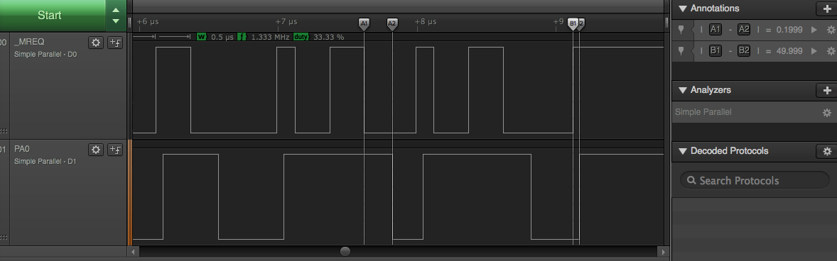
The top line is the _MREQ from the Z80A again, but the lower trace is the output of PA0 (which I have various ifdefs to turn on for debugging). PA0 is going low at the point where the code is ready to present some data on the databus to the Z80A. And PA0 goes high right at the point we tristate the data lines. I am still in the order of 200ns before I get some data on to the bus, but given the 360ns window, that is not that bad. Also keep in mind that toggling PA0 wastes time, so the timing should be slightly better with the DEBUG ifdefs off.
_IORQ processing uses the negative edge for the interrupt. _IORQ cycles are longer (I should look it up, but they seem to be over 1000ns ), so we have more time to spare. There is a possibility that an _MREQ interrupt could be being processed when an _IORQ occurs (since the _MREQ service routine might be polling for a negative edge of _MREQ). For this reason the _IORQ interrupt has a higher priority than the _MREQ one, so it can ‘pre-empt’ the _MREQ one. I will point out here that if you use SDIO stuff in STM32 code you end up with a CPU interrupt on SDIO_IRQHandler(), so that interrupt needs to be a lower priority than both the _IORQ and _MREQ ones (Note to self; ARM interrupt priorities are slightly confusing in that a lower priority means a ‘higher’ priority number)
So the _IORQ code is much the same as for the polling method (though I have fixed a few bugs). We look for writes to the ROM select register at $DF00, and since I am emulating some of the upd765 Floppy Controller chip, I look for reads and writes to $FB7E and $FB7F. Emulating the floppy chip is reasonably complicated. I don’t emulate it all, but I have extended from the polling code. Notably;
- I can actually load multiple blocks at a time (which is missing from the polling version of the code).
- It has a basic understanding of Extended DSK files
- It can do ‘WRITE DATA’ to save data to a DSK file (I have only really tested this with BASIC programs).
- It can load all the tracks of a disk.
The last point is the major reason I had another look at this . The polling code could only load the first 96K of a DSK file into memory and read it. Now that I have a main thread and interrupt driven _MREQ and _IORQ service routines, when the floppy emulation code needs to do a SEEK or RECALIBRATE (ie. seek to zero), then it triggers the main thread into reading the appropriate track into a buffer before continuing. This way I only need a 6KB or so track buffer to be able to do everything.
So I still have to do a ‘magic write’ from the Amstrad to &FB7E to get it to swap disks. So in BASIC if I do
OUT &FB7E,5
Then that means load CPC005.DSK from the SD card. The polling code used to do a nasty reset of the STM32 in order for this to all work, but now the ‘change disk’ is communicated through to the main thread, which triggers the reload.
What’s missing?
Heaps! It’s best at loading ‘pretty normal’ disks without weird copy protection. It still does not understand READ TRACK and some of the more obscure floppy commands, but a fair bit of stuff from the 1980s loads.
The WRITE DATA seems to work, but is quite slow. I essentially buffer writes to a whole track, and it only really gets flushed when the Amstrad does another seek. I probably need two track buffers to do it better.
Installing
As per part 1, you need a ARM gcc build environment. Before you enter ‘make’ you’ll need the Discovery std perif includes from st.com, and you’ll also need 16K rom files for Parados and Maxam put in the roms folder. After a ‘make’ you should end up up with a bin, elf and hex file. If you can get dfu-util installed you should be able to use the transfer.sh script to push the firmware to the stm32f407 board via USB.
Format a micro SD card, preferably with a 1st partition under 4GB that is formatted in FAT32, then get some Amstrad CPC DSK images, and copy them to the SD card using names like CPC000.DSK, CPC001.DSK and so on.
Hook it all up to your Amstrad CPC 464 (yep, it is still just for the 464) per the wiring details. You should be able to power the stm32f407 board from the Amstrad OK.
When you power on your 464 you should see ‘Maxam’ and ‘Parados’ in the initial onscreen banner. That means that the ROM emulation stuff is at least working.
In theory it resets to disk CPC000.DSK the first time you use it (otherwise enter this in BASIC):
OUT &FB7E,0
Then try a directory of the disk:
|A
CAT
If you see one or more files, it is all working. Changing disks is via the OUT command still. eg. to change to disk CPC025.DSK, you would enter:
OUT &FB7e,25
If CPC025.DSK does not exist, it will auto reset back to CPC000.DSK. And, per normal for an Amstrad you generally find the main program on the disk and enter a RUN command to load and run it
RUN "ELITE64E"
The code
I’ve updated the main master branch with this interrupt based code, and put the polling code into a separate branch ‘polling_version’.
https:/github.com/amstradcpc-rom-emulator