So I finally bought a Dragon 32
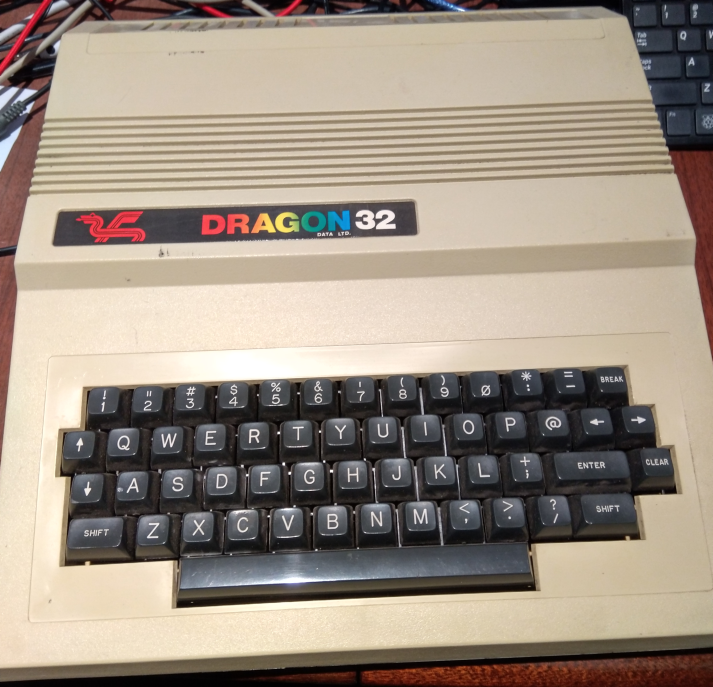
I’d been meaning to get one for quite some time, but they rarely come up for sale in NZ, and ebay postage from the UK is not exactly cheap. Anyway, I caved in and bought this one from the UK. It was untested and had no power supply. I remember when the parcel arrived I was worried that they forgot to pack it as the parcel was so light. It is quite a light computer given its physical size.
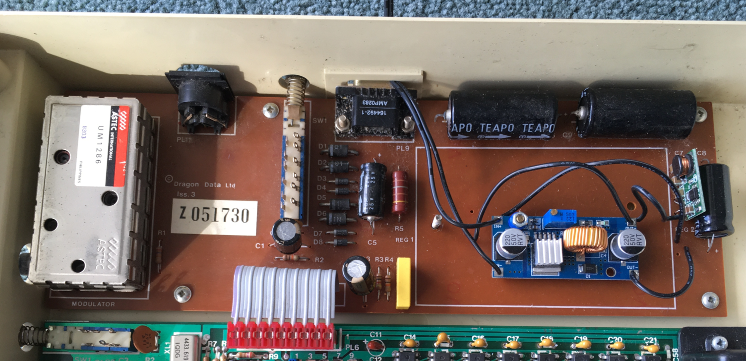
So first thing was to see if it worked. As I had no power supply I had to rig one up. So, first off, the ‘external power supply’ is really just an AC transformer. The rest of the power supply is inside the case at the back (on the brown PCB to the right of the RF modulator
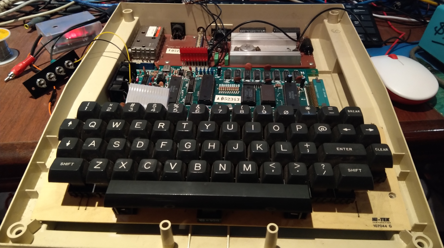
As I did not have an AC transformer of the same specs as the Dragon one, I thought I would just bypass it all initially. In the photo above you can see the red connector where the voltages come in from the power supply board. This has +5, +12 and -5 volts coming in on various pins. So as a first test I just soldered some wires to allow me to connect an ATX PSU to it. I just had a 7905 regulator stuck on the ATX -12 in order to get -5. That was enough to get me a working Dragon! Before long, I had a audio input cable setup on the cassette port and I was able to load a few games
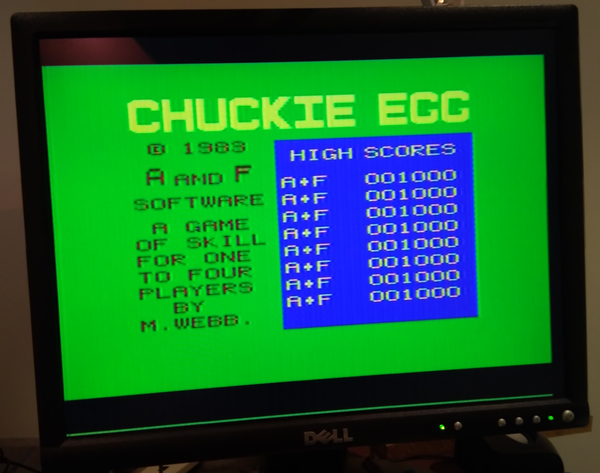 The bright green background and strong red, blue and yellow colours brought back a few memories. I had a Dick Smith VZ-200 when I was younger which has the same 6847 video chip and same colours. I am sure if you under the age of 40 you might look at the video output and go ‘what the!’. But the 6847 was a cool simple off the shelf video chip in the early 1980s. A side story here is that I had an older brother at University doing engineering in the early 1980s and he did a semester on Microprocessors, and they studied the Motorola 6809 CPU. I ended up getting a lot of reading material on the 6809 and bought one, alongside a 6847 and was able to build a small homebrew 6809 system on a vero board. The 6847 made video very simple because it had a built in character ROM, so you could attach 2K of static RAM to it and get a picture on a monitor (which was only black and white as colour was ‘too hard’ for me back then). I also did a lot of 6809 assembly/machine code as well, and I always remember the 6809 having one of the nicest assembly languages.
 Anyway …
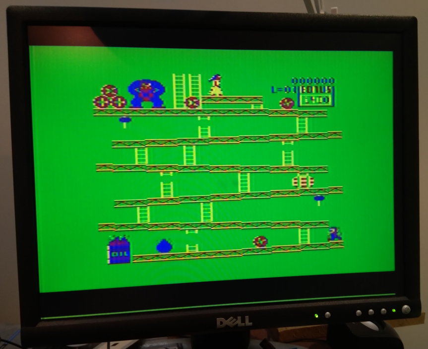
To load a game I would type CLOADM on the Dragon 32 and then use mplayer or similar on a PC to play out the audio WAV file. Assuming it loads, generally the game does not start. You have to type EXEC on the Dragon. One oddity I noticed is that you cannot type very quickly on the keyboard (which I later discovered is an oddity of how the keyboard is scanned). However the keyboard is one of the coolest sounding keyboards of all the old computers I have. There is just something very satisfying about typing on it.
Many of the games seem to want a joystick and the Dragon used Analog joysticks with a now obscure DIN connector. As a temporary joystick solution I’m using an Arduino analog joystick effectively soldered directly to the board (as I haven’t been able to find the appropriate DIN plug). This sort of works, but I don’t think the resistance range of the potentiometers is quite correct.
So I had it running and the ATX PSU setup was purely to confirm it worked, so then I tried to work out a better power supply setup. This was the beginning of a series of mistakes on my part. First I decided I would use a 5V 2A plug pack with a DC 2.1mm plug and have that go directly into the 5V line of the Dragon, and to have a DC-DC boost converter that converted +5V to +12V to get the +12 line, and a DC-DC inverter thing that takes +5V in and generates -5V. I wired this up, got it all working then left the Dragon for a few days.
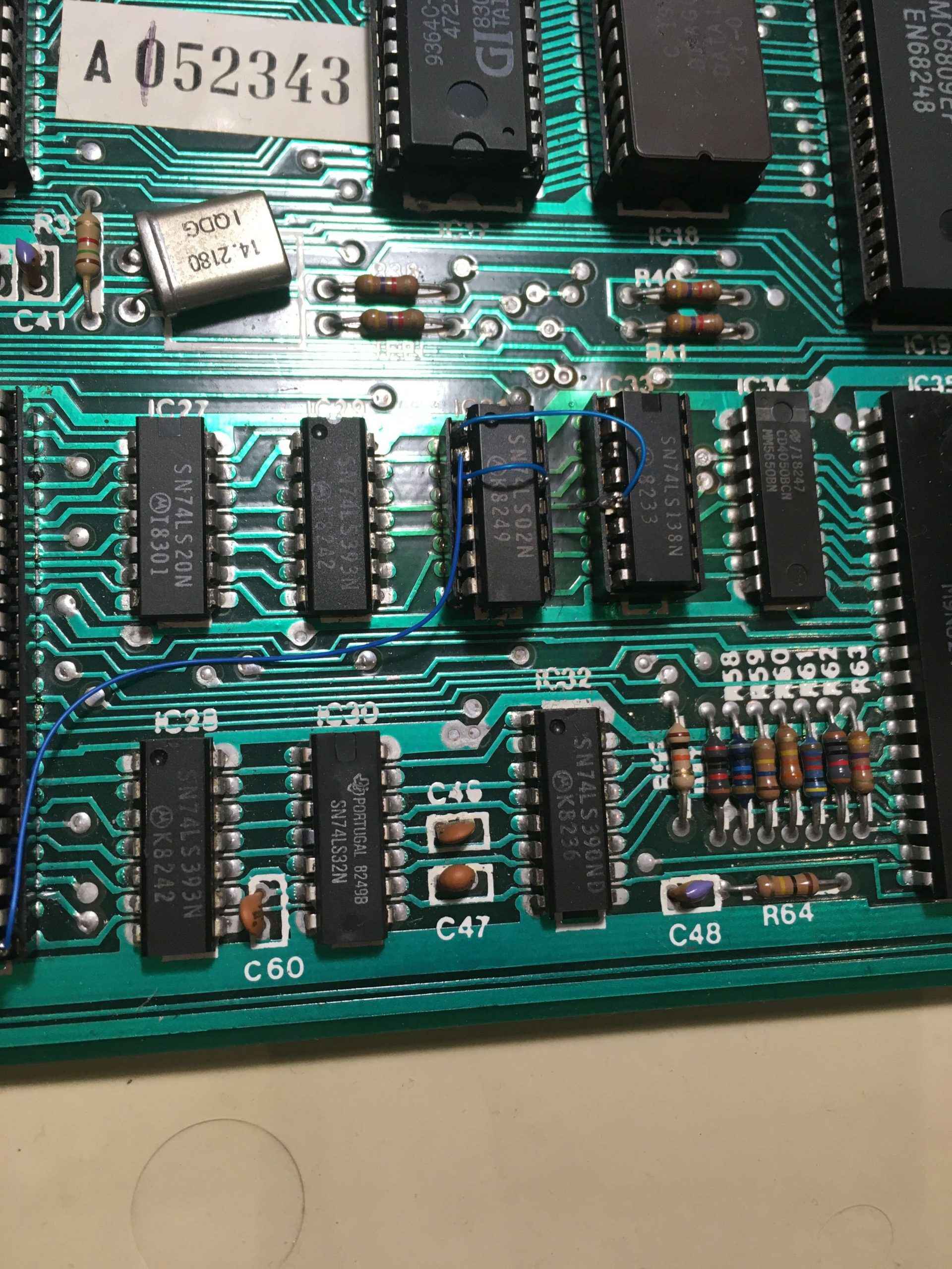
Then I decided to power it on. Without using enough brain power I took a DC 2.1mm lead on my desk and plugged it in to the DC 2.1mm socket that was expecting +5V. Of course I had just plugged in a +12V DC power supply. Bad. Bad. Bad. I quickly unplugged once I’d realised my error. But the damage was done. The Dragon no longer worked and I was very annoyed with myself. Then ensued an evening of troubleshooting and desoldering trying to get it going again. These ended up being the dead chips:
- Pretty much all the 4132 DRAMs were dead.
- The 6821 that drives the keyboard was dead.
- The 74LS783 (aka 6883) was dead.
Blowing up the 74LS783 was particularly annoying as it was a very rare chip until recently. Fortunately years ago, I had tracked one down thinking “It’d be nice to make a Dragon 32 on a breadboard one day …” so I used my one spare to get it going again. I just used 4164s instead of the 4132s. I think if you check the 74LS783 datasheet you need to use 128 cycle refresh 4164s. So lately I’ve seen a few youtube videos on ‘fake old chips’. It is baffling how a chip like the 74LS783 was super rare for many years, then within the past year, a quick search of ebay will show you quite a few of them. I actually ordered five of these ‘recently surfaced 74LS783’s. I should properly test them ( I just noticed recently that the labelling on these extra 74LS783s is not even straight … which is not a good sign).
And so the Dragon worked again.
But I thought “Don’t make the same mistake again! Make sure your DC 2.1mm input plug is for +12V and then you cannot possibly screw it up again”. So then I came up with a scheme where you have +12V in. That would directly drive the +12V line of the Dragon, but then I’d have a LM2596 adjustable board to get +5V and still use that +5 to -5 converter to get -5V.
However in the midst of all this rewiring and soldering I was touching a multimeter probe against the +5V pin of the PSU input and briefly touched it to the pin next to it which is the +12V input. Doh!
More troubleshooting and I had blown up two of the 4164s but the 74LS783 and the 6821’s were all good.
So finally I did enough surgery inside such that a lot of the old linear power supply electronics were removed and replaced with the modern stuff and I just had a DC 2.1mm socket hanging out the back for the +12V input.
The final thing I did was to do the Dragon 32K to 64K upgrade, now that I had replaced all the 4132’s with 4164s. It’s worth looking at the very old scan of this upgrade (as it has a small schematic as well).
 So the Dragon did have a floppy drive expansion back in the day. Actually it had a few. The main one was based on a WD2797 floppy controller, not unlike what I’ve emulated on my MSX and Spectravideo ROM and floppy emulation projects, so the logical thing to do was to hook up a STM32F4 board to the cartridge slot. Stay tuned …