The Dragon 32 could be expanded to include a DOS cartridge. This contained a small DOS ROM and Floppy Disk Controller chip. You plugged a 5 1/4″ drive to the cartridge and you had a working floppy drive. There were a few companies that made similar expansions. Some are documented on the World of Dragon Peripherals page. The DOS cartridge made by Dragon Data used a WD2797 Floppy Disk Controller. This belongs to the WD279X/WD179X family of floppy controller chips. It is almost the same as the WD2793 that is emulated as part of my MSX ROM and floppy project. The idea then was to port that to work with the Dragon 32.
So essentially we’ll take a cheap stm32f407 board and connect it directly to the bus of the Dragon 32. The stm32f4 is good as it has lots of 5V tolerant pins. As the CPU in the Dragon accesses memory, it will fire an interrupt in the stm32f4 board such that it can pretend to be a ROM in real time. In this case it will also pretend to be a WD2797 floppy controller chip and a 6 bit latch.
Some technical details. The Dragon has a 40 pin cartridge port. This carries all 16 address and 8 data lines as well as power and some control pins. Some important ones:
- E and Q clocks.
- _CTS . This is the $C000 – $FFEF chip select for a ROM cartridge.
- _P2 . This is a peripheral chip select for $FF40 – $FF5F.
- CART . This goes to CB1 of PIA1.
- _NMI . The 6809E _NMI interrupt.
For the 6809E CPU, the main ‘action’ during the clock cycle is when E is high, so E connects to PC0 and will fire an interrupt on the stm32f4 when E goes high. Per my other projects, it takes over 100ns before you get to the first line of your interrupt service routine, so part of the ‘E’ high is wasted, but its high for over 500ns which is enough time to do everything.
For the Dragon DOS cartridge, an 8K ROM containing DragonDOS is selected via _CTS, and the WD2797 is addressed using _P2 to appear at addresses $FF40 to $FF43, and _P2 is also used to map a small latch at $FF48. The latch carries drive select and motor signals, as well as a pin that allows _NMI to be disabled or not. This highlights one of the main differences to the MSX and Spectravideo ROM/Floppy projects. The WD2797 actually sends interrupts to the 6809E CPU, rather than having it poll to see what the state of DRQ and INTRQ are. Effectively:
- DRQ drives the CART pin
- INTRQ goes through some gates and is inverted to drive _NMI. Essentially, if you have a ‘1’ written to bit 5 of the $FF48 latch, then when INTRQ goes high on the WD2797, the 6809E will get an _NMI interrupt. If bit 5 of $FF48 is a ‘0’ then INTRQ is effectively masked from the 6809E.
The use of interrupts stumped me for quite a while when trying to modify the msx-rom-and-floppy-emulator code. The main lesson is that it’s very easy to send interrupts too fast to the 6809E. As an example, when a ‘read sector’ is performed, first the 6809 writes a ‘read sector’ command, then when the first byte of that sector is ready, the WD2797 would send DRQ high (which ends up triggering an FIRQ, or triggering the end of a SYNC instruction), the 6809 then reads the ‘data’ register which clears the DRQ, then moments later the WD2797 sends another DRQ. After the 256’th byte of data is read, INTRQ goes high and ends up firing an _NMI. What I found is that I could easily send another DRQ or the final INTRQ before the 6809E was ready to accept the next byte. This meant data would go ‘missing’ and behaviour would be a bit ‘flakey’. Even when I thought I had the ‘read sector’ stuff working properly there were still some games that failed in strange ways. These were eventually rectified simply by slowing down the interrupt rate even more.
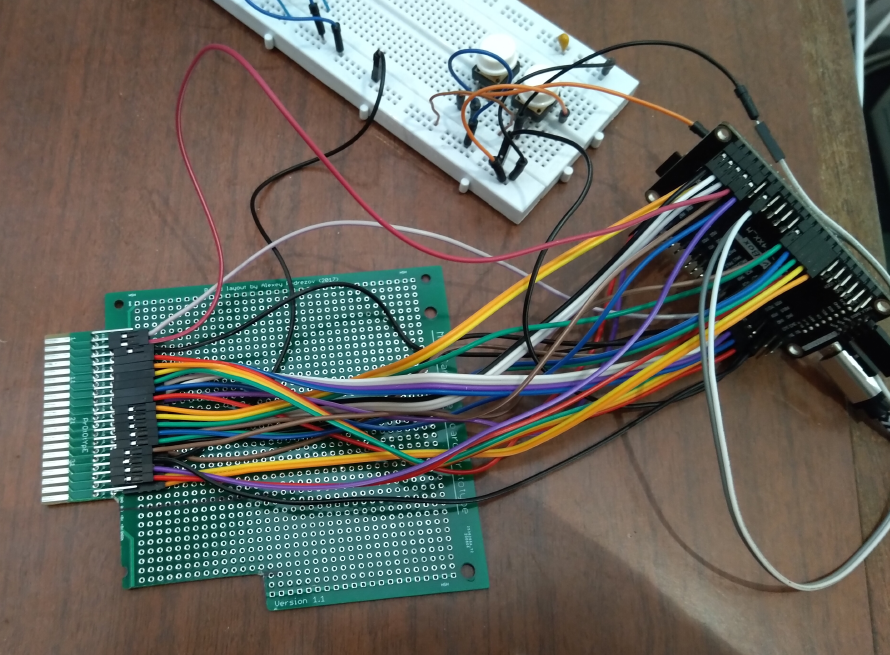
Here’s my prototype setup. I had quite a few spare MSX cartridge prototype boards left over from my MSX project, so I just got out the hacksaw and cut the edge connector down to 40 pins, and also removed part of the lower left edge to get it into the cartridge slot. Then I just soldered in some right angle header pins so that the arduino jumpers could run from the stm32f407 board to the cartridge slot. I also have two push buttons on the breadboard for the ‘NEXT disk’ and ‘PREV disk’ buttons. That’s all there is.
It works a lot like the MSX floppy and ROM emulator
- You put a FAT32 partition on a micro SD card
- Make a ‘dragon’ directory in the root of the micro SD card
- Copy VDK disk images and ROM files to the ‘dragon’ directory. You have to be mindful of the order you copy them, as the NEXT and PREV buttons will step through them in the order you copied them, not alphabetical.
- In order for the Floppy emulation to work you need a file in the root of the micro SD card called ‘dragondos.rom’. I’ve tested mostly with Dragon DOS 1.0, but SuperDOS E6 or E8 seem to work. It just has to have the filename ‘dragondos.rom’
- There is a Dragon native ROM called kcdfs. You compile it with lwtools and that gives you a menu.rom file. Just put that in the root of the micro SD card as well.
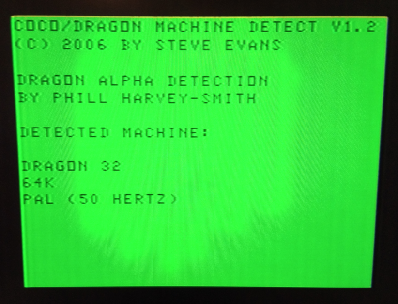
Plug it in to the Dragon. I generally have the stm32f407 board powered separately (rather than tied to the +5V of the Dragon 32). The stm32f407 will boot up, read the micro SD card. If it finds the menu.rom, it will make it appear as a cartridge to the Dragon when you power it on. It should look like this:
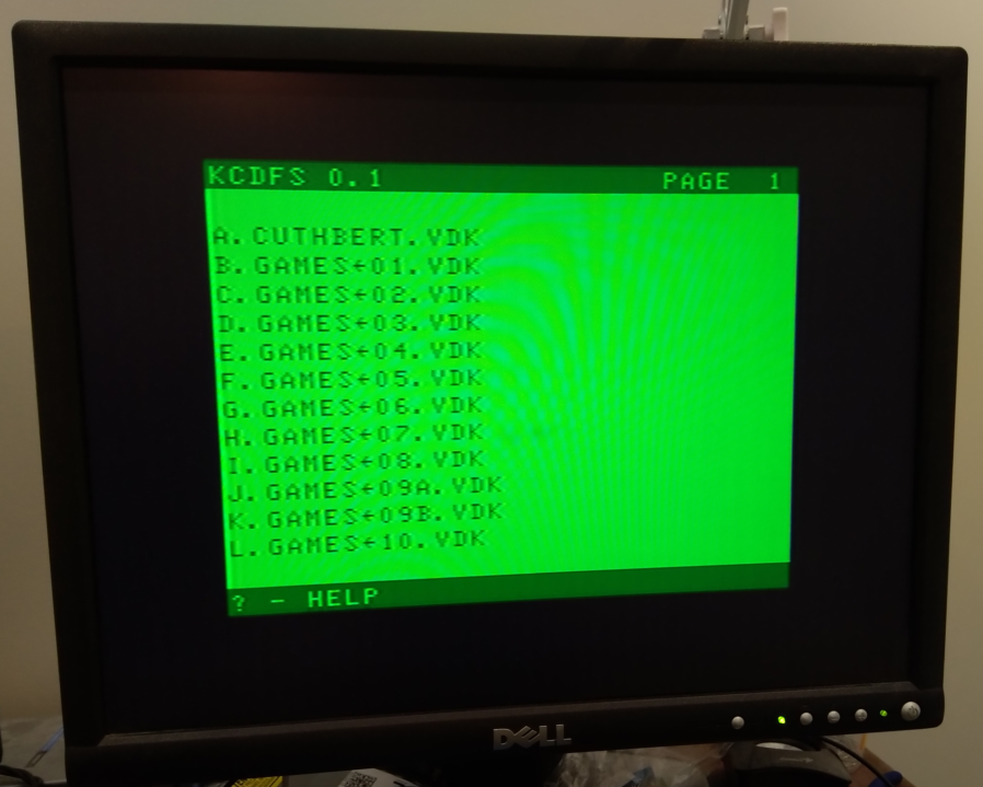
Kcdfs will communicate to the stm32f407 board, ask for a directory listing of the ‘dragon’ directory and present it on the screen. Its a ‘paged’ interface, so if you have more than 12 files, just press ‘2’ for the 2nd page of 12 files, ‘3’ for the 3rd and so on. ROMs and VDK files are all mixed in together like this
If you press a letter ‘A’ through ‘L’ it will :
- If you selected a ROM file , that ROM file is now presented as a cartridge and the Dragon is forced to do a COLD start. It should reboot into the cartridge.
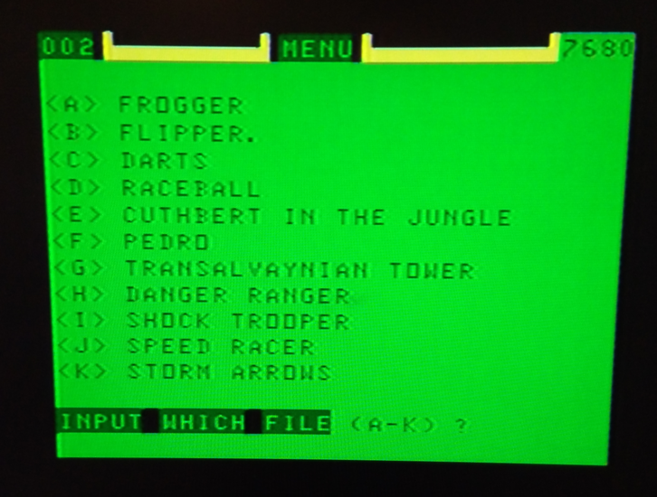
- If you selected a VDK file, the ROM file is presented is switched to the dragondos.rom and the Dragon is forced to do a COLD start. You should see the ‘Dragon DOS’ banner when it reboots (assuming you put Dragon DOS in the dragondos.rom file). If you type DIR you’ll probably see a directory listing of the disk you selected. You can LOAD or RUN etc to run programs off the virtual disk. Alternately you might type BOOT if its a bootable disk.
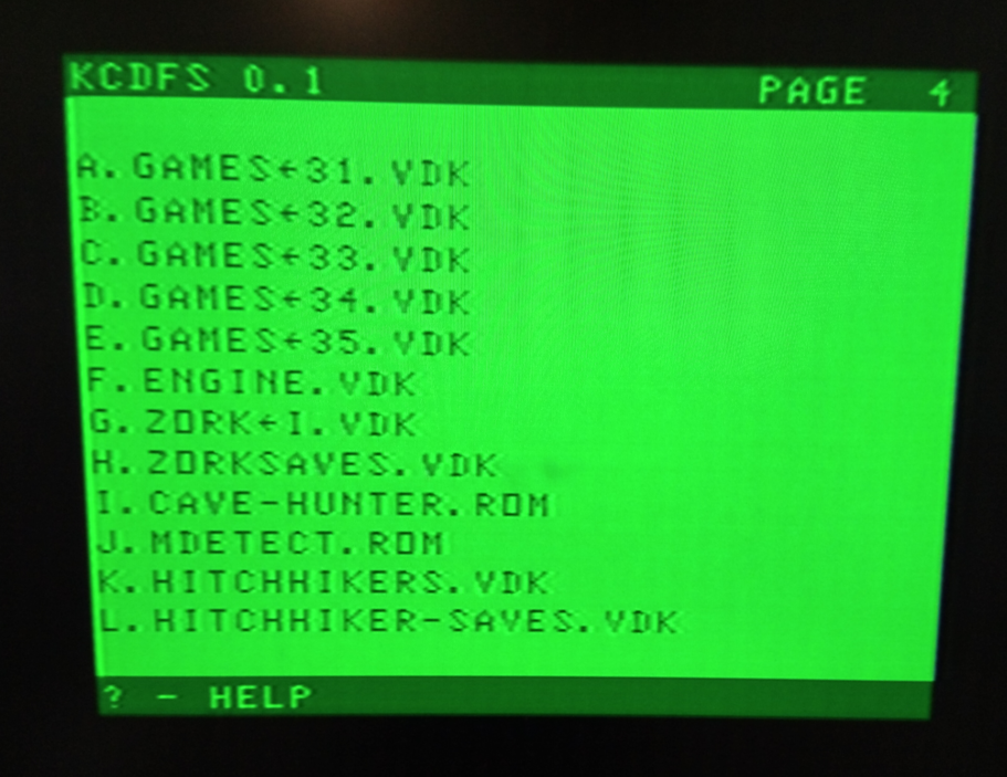
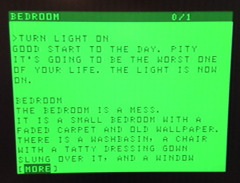
So the NEXT and PREV buttons are handy if you need to access a 2nd disk or a gamesave disk. When the game asks for the save disk you press the NEXT key. When you need the original disk again you press PREV. I ran the infocom games a fair bit during testing. In that last screenshot, in order to run Zork I would select ‘F’ to load the ENGINE.VDK. Then load the BIN file you need to load, then press NEXT to get the ‘ZORK->I.VDK’ disk loaded, then run the special EXEC command to load from the ‘ZORK->I.VDK’ disk. Then in the game when it asks for a save disk, press NEXT again, do the save, then when it asks for the story disk, I just go PREV. If you are interested in the infocom games for the Dragon look at this thread on worldofdragon. I’ll also note that if you leave out the menu.rom on the micro SD card, then it will default to loading the first disk or rom you have in the ‘dragon’ directory, and you can use the NEXT and PREV buttons to step between disk images.
If you want to return to the kcdfs menu, you need to reset the stm32f4 board. Sometimes I unplug power on the Dragon, then hit reset on the stm32f4 board. Sometimes I can just hold in the reset button on the Dragon while tapping the stm32f4 reset button.
So what works and what doesn’t work? Well, a lot of stuff seems to work. I have not implemented read and write track, so I don’t think formatting a disk will work. If I want a ‘blank’ disk usually I just make a copy of ‘cuthbert goes walkabout’ and delete/kill the one file on the disk.
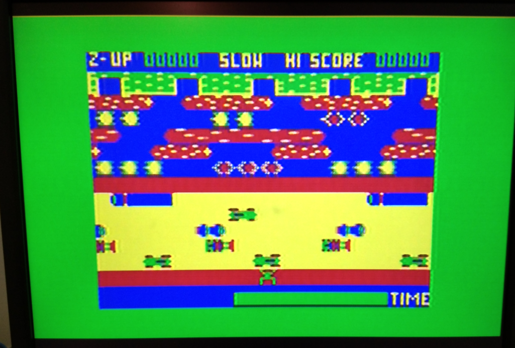
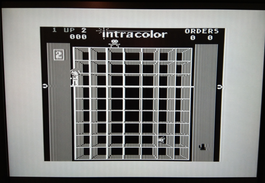
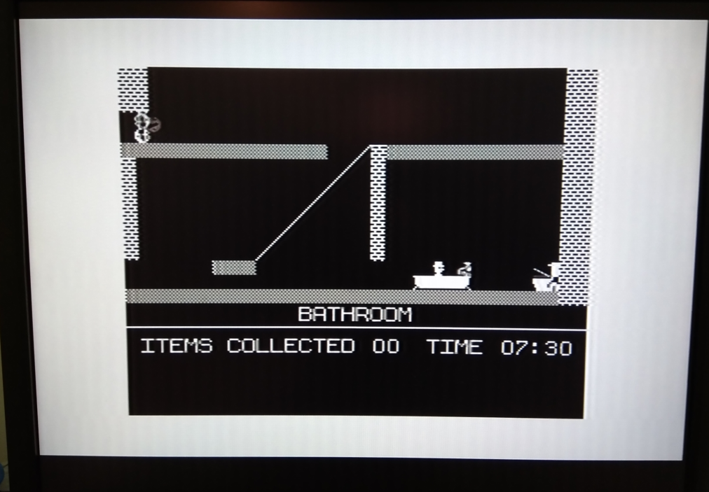
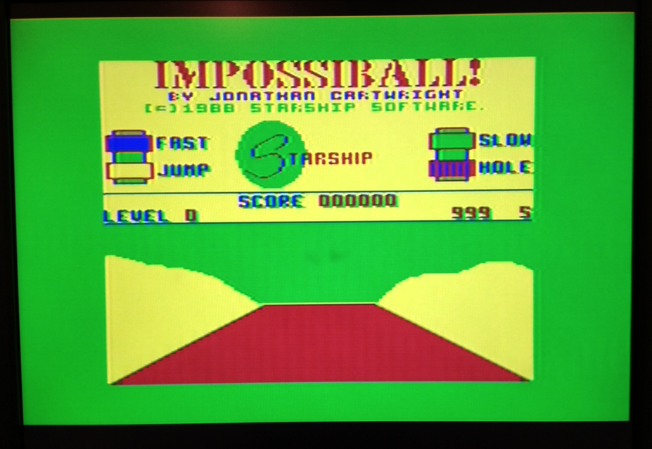
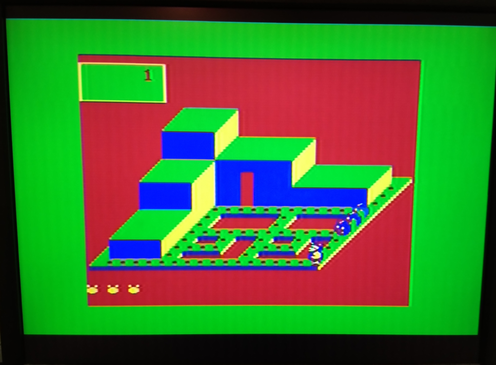
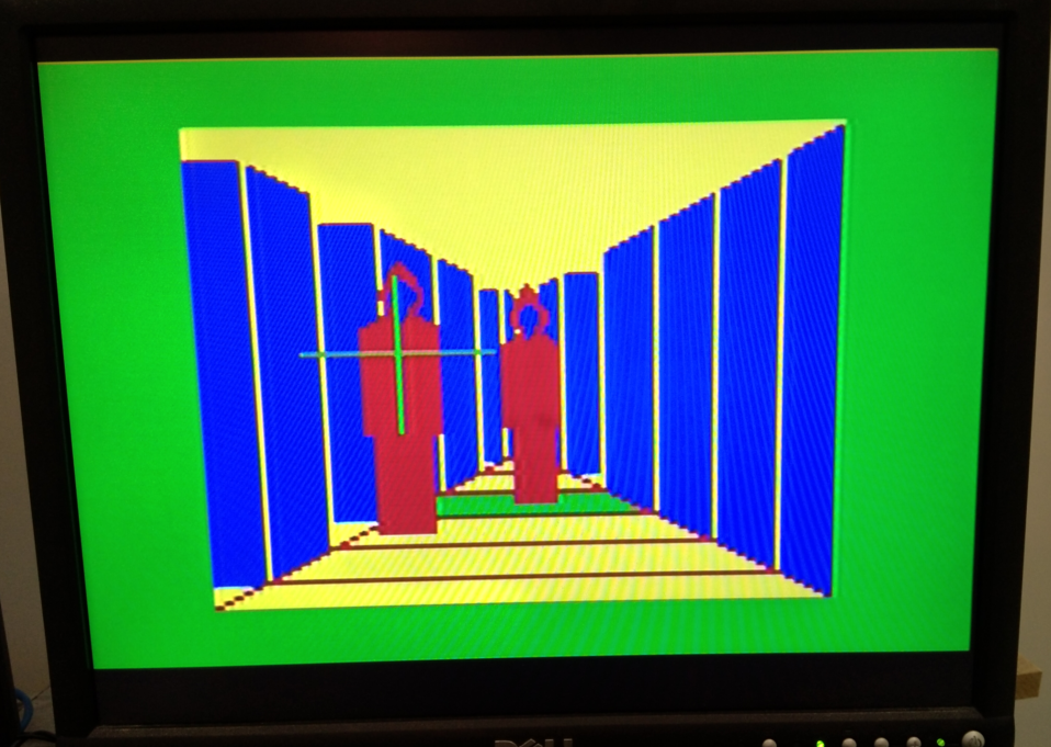
Here’s some screenshots
 |
 |
 |
 |
 |
 |
 |
 |
 |
 |
https://github.com/kernelcrash/dragon-rom-and-floppy-emulator