So that Galaksija I made up was quite fun to build and get going. And I’ve found a few other homebrew projects like that. Recently I’ve built an Amiga 500++ (thanks Rob), and then I came across the Omega MSX2 . Sergey has designed a set of boards that make up an MSX2 home computer (ie. compatible with MSX and MSX2 based home computers from the 1980s and early 1990s). One board is the main circuit board. The other is for mounting keyswitches so you can have a full mechanical keyboard. Like the other projects, you buy the circuit board(s) , then source the parts yourself and get busy with the soldering iron. Most parts are available new, and there is a handful of (older) parts you need to source from ebay or aliexpress or similar.
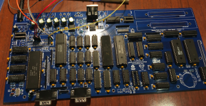
I bought the Omega boards back in February, and ordered ‘most of the other parts’ in February too just before everything went in to lockdown here. Fortunately my ‘box of chips’ already had a few Z80As, an AY-3-8910 (sound chip) and even a 9958 video chip with matching socket (which I thought would come in handy one rainy day). I had most chips and no keyboard. I started making it up during lockdown anyway. I thought I would ‘figure something out’ when it came to the chips that I didn’t have and the keyswitches I did not have.
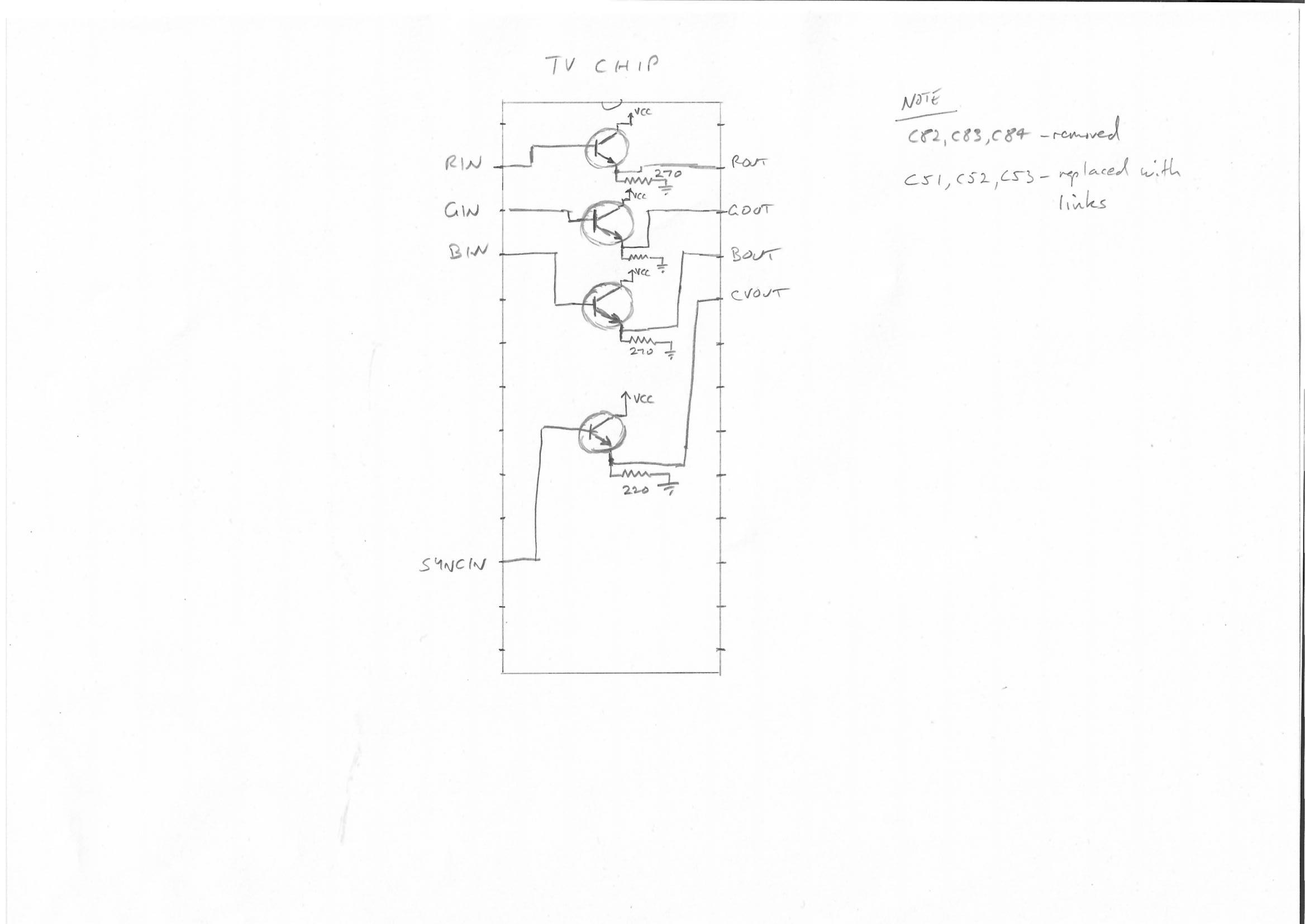
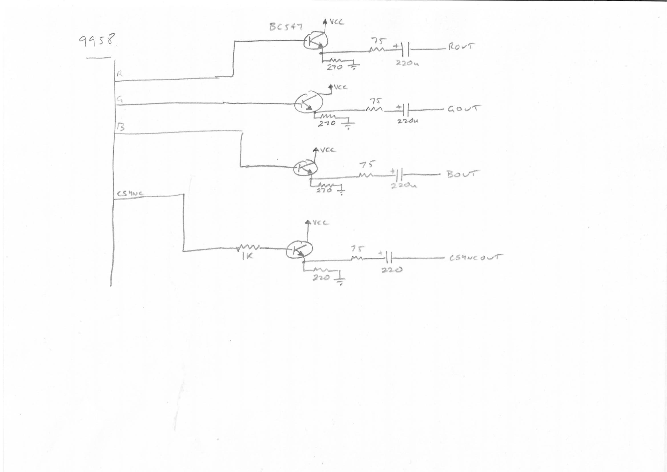
So when I had it soldered together, I was still missing the RP5C01 RTC chip and the special Sony TV chip. I was told that if I installed C-BIOS on the boot ROM, then it would still boot without an RTC chip. The Sony TV chip was used to convert the RGB outputs of the 9958 video chip into composite/s-video and more important for me, it buffered the RGB signals. So that meant figuring out a buffering circuit instead of the Sony TV chip. I eventually came up with this.
That was good enough to get a picture of the C-BIOS logo via a Gonbes GBS-8200 (I’ll note here that I used my own shmups mod with an ATTINY85 to do line doubling type modes).
What next?
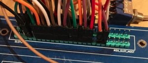
The obvious thing (to me) was to hook up an STM32F407 board to emulate a ROM cartridge (since I had no real cartridges). I had not soldered in the edge connectors to the Omega board, so soldered pin headers instead to make it easier to hook up the STM32F407 board.
I modified some of my older code and had a simple polling setup to expose a 16K or 32K ROM when the appropriate _CS1 or _CS12 line went low. That was good enough to get Antarctic Adventure and a few other games to go. MSX has a lot of much larger cartridges as well that use ‘mappers’ (extra logic that allows some form of bank switching for the cartridge). I decided that ‘later’ I would look into all these mappers. The next problem I soon hit was that a lot of games that use joysticks still want you to ‘press space’ or ‘press 1’ or ‘press 2’ to start the game, and I had no keyboard so that was not possible. I ended up hooking a 74LS138 into the keyboard row outputs, and then worked out a rudimentary way of shorting some of the 138’s outputs with the column inputs. And so I could now press space, 1 or 2 and avoid all those Antarctic Walrus’s.
I was still keen to have a full working keyboard, so I hacked at my keyboard-matrix-emulator enough to have a PS2 keyboard act as the full keyboard matrix of the Omega (the code is in the omega-msx2 branch for now). Originally I combined the keyboard emulation into the ROM emulation, but after a few issues I separated out the keyboard emulation into another STM32F4 board.
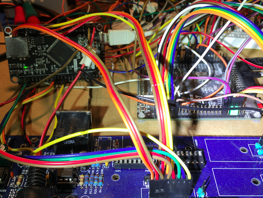
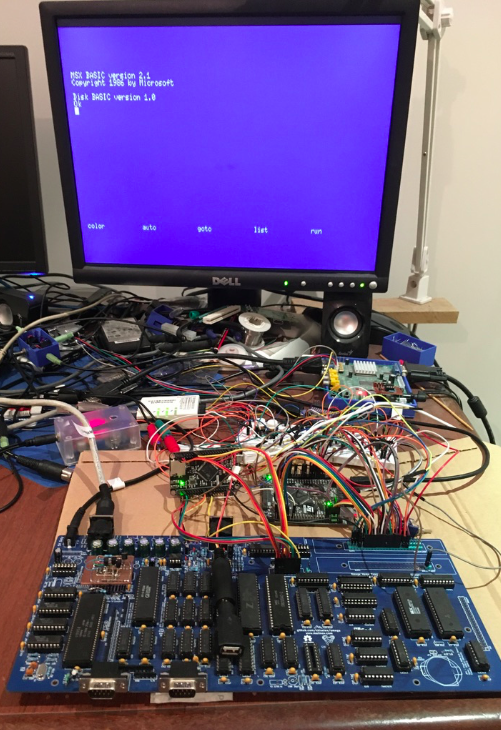
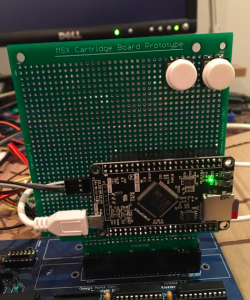
In the photo, the stm32f407 board on the left is called a DevEBox board (on aliexpress). It has a PS2 mini-din socket attached to it for a keyboard, and it’s jumpers connect straight to the Omega’s keyboard connector. The stm32f407 board on the right is connected to the slot connector to emulate ROMs, the FDC controller and part of the RTC chip (read below). I think some people call this a ‘Black VET6 board’. It has a battery and micro SD slot.
Of course now I wanted to boot into BASIC. The Sanyo PHC-23 and Philips NMS-8250 ROMS are the suggested ones to use (for NTSC and PAL respectively). So I tried the ROMs. Of course the Omega did not boot .. which I knew would happen since I was told a normal MSX2 computer depends on the RP5C01 RTC chip (unlike C-BIOS).
Out with the Z80 disassembler and I worked out that the main use (from my perspective) of the RTC at boot time is not for telling the time, but for retrieving the battery backed up config data. The RP5C01 chip has two thirteen byte RAM banks that are used for things like the screen resolution, foreground/background colour etc. ie. these are remembered after a power off/on. From what I could tell, a check is performed to see if the data in the RTC is valid, if its not, some default values are loaded in to it, then later on during the boot the RTC is interacted with directly to pull out this config data. It didn’t appear to pull all the values and then use them from the MSX computer’s RAM. It just grabbed them directly when it needed it (I could be wrong here). Anyway, I thought if I could somehow emulate these two banks of thirteen bytes, I might have a chance of booting in to BASIC.
Emulating two banks of 13 bytes sounds easy. However, I initially got things very wrong due to a misunderstanding of the MSX slot architecture. The default is that you can access ‘memory’ in a slot, but not IO addresses. So my STM32F407 board was plugged directly into one of the ‘slots’ for cartridges. That meant the address lines went through buffers, and also the databus was buffered through a 74F245. So the STM32F407 board would pick up a ‘write’ to an IO address, but the Z80A would never see the data for a read from an IO address. After some confusion, and a nice response from Sergey, I realised I should have been using the _BUSDIR signal which is specifically for this. I just needed to drive that low when the Z80A was trying to do a read from 0xb5 (the IO address of the RTC chip).
So I finally got that working (and fixed some bugs with my code) and I could boot to BASIC. I had a keyboard. I could type stuff. Various other issues ensued, but I won’t go into them. I got so far as using the cassette interface to load a game and then started thinking about what to do next. I’d emulated the upd765 Floppy Controller for the Amstrad, and I always thought I should try to emulate the main other family of Floppy controllers; the WD179X ones … like what you would have in most MSX/MSX2 computers.
Then I spent the rest of lockdown working out how to do it. I had a lot of trouble (I often do). Per my earlier posts you have to write ARM assembly code that is very very fast. As I wanted to use the SDIO stuff built in to the STM32F4’s I needed to use interrupts again. If you’ve read any of my previous posts you’ll note that I generally interrupt at the end of the previous bus cycle (ie. the positive going edge of _MREQ). That generally means the interrupt service routine is starting some time after the end of a cycle and before (or just after) a new cycle starts. The reason is that the STM32F4 is going to chew through at least 100 to 150ns after a signal edge before your interrupt service code starts. If you interrupted on the negative edge, then you are often a long way into the bus cycle and you don’t have much time left. So in my Amstrad code and the Electron code I was interrupting at the ‘end’ of the previous cycle and immediately polling for the start of the real cycle.
So I decided to interrupt on the negative edge of _MREQ! The rationale was; the MSX2 seems to have pretty long bus cycles (they seem longer than what I would expect for a 3.58MHz Z80A, like there is a compulsory wait state).
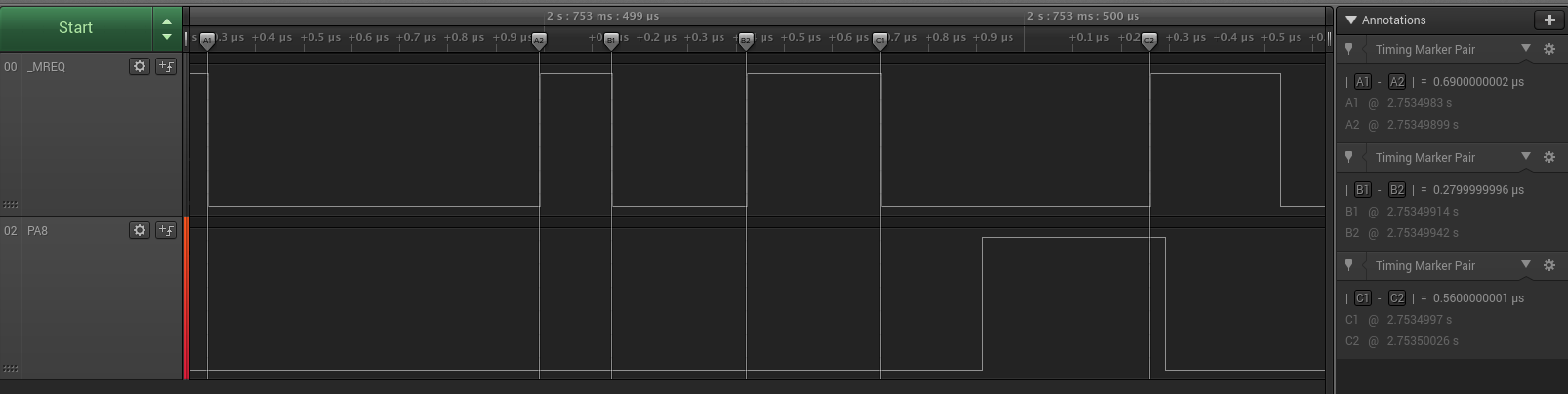
Per the sample above, a normal memory cycle seems to be 690ns, a refresh cycle seems to be 280ns and a shorter M1 cycle is about 560ns.
I was also thinking I could use a lot of floating point registers as general purpose integer registers in order to make the code fast. I’d used the floating point idea with the Electron last time (but I haven’t updated the Amstrad code to use them). Anyway , that was the idea. I thought if I could not get it to work, I would go back to always interrupting on the positive edge of _MREQ.
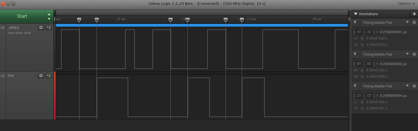
The ROM emulation timing looks like this. I’m taking about 250 to 270ns to get from _MREQ going low to being able to get some data on the bus during a Z80A read cycle. So thats 100 to 150ns chewed through in the interrupt response, then at least another 100ns to work out what to put on the bus, un-tristate it and present it.
I was not going to write a Floppy Disk emulation from scratch, so I used the same technique I did last time. Find an emulator with source (I chose fMSX), put lots of printfs in its Floppy emulation code, and boot some floppies and figure out how it operates , then hand convert the C code into the convolution that is ARM assembly using floating point registers as globals as much as possible instead of RAM.
So I eventually got it to work. It works, but it’s a ‘work in progress’ so far as finishing touches are concerned, but the deal is:
- Format a microSD card with Fat32 (I always make a smallish <1GB partition at the start of the card).
- Create an ‘msx’ directory on the microSD card.
- Copy some roms and dsk images to the msx directory. However, note that:
– ROMS bigger than 128KB won’t work
– If its a ‘Konami without SCC’ ROM then you have to rename the ROM file to end in .konami4 . eg. usas.konami4
– If its an ASCII8 ROM then rename it to end in .ascii8
– If its an ASCII16 ROM then rename it to end in .ascii16
– If its a simple 16K or 32K ROM then just leave it with .rom as the suffix
– Currently there are no other ROM types supported
– If its a dsk image then just leave it with the usual .dsk suffix. It should handle single sided and double sided disks. - In order for .dsk loading to work at all, you need to put a disk ROM in the root of the SD card, and name it ‘disk.rom’. I will note that I have done all my testing so far using the NMS 8250 disk rom with MD5 0ed6dbd654da55b56dfb331dd3df82f0 . Other disk ROMs may or may not work. I just haven’t tested them.
- It tries to simulate a single A: drive. I need to look into the whole ‘shadow disk’ thing , as the way this works is not quite the same as a real MSX2 computer.
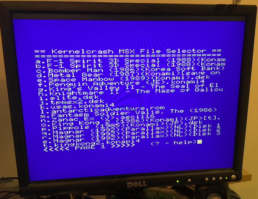
- There are two possibilities on boot. If the stm32f407 board has just been reset AND you have a rom called menu.rom in the root of the SD card, then it gets loaded and executed. There is a simple MSX native ‘file selector’ called kcmfs. So if the menu.rom for kcmfs is in the root of the SD card the MSX computer boots and shows a menu of the files in the msx directory of the SD card. You select one, the MSX computer reboots and starts up whatever you selected. If you don’t have a menu.rom, then after reset of the stm32f407 board it loads the first rom or disk in the msx directory of the SD card.
- If the current file is a ROM file then it will work like a cartridge plugged in. If its a dsk file then the disk.rom is loaded as a cartridge and the floppy dsk image will start to load through the emulated WD279X.
- If you want to cycle to the next dsk or ROM image in the msx directory:
– Turn off the MSX computer
– Push a pushbutton connected to PA1 on the board.
– Turn on the MSX computer. - There’s also a ‘Previous button to step backwards through the file list. So press the ‘Previous’ button connected to PA2. (Note the points above about turning off before hitting the button).
- If you’re using the kcmfs file selector, then you can power off the MSX computer, reset the stm32f407 board, then power on the MSX computer in order to get the menu again.
- If its a multi-disk game, and it asks you part way through to ‘insert disk 2’, then pressing the ‘Next’ button should work (so long as you copied the two disk images to the SD card in the right order. See note below).
- Like a lot of stuff that uses FATFS, the order of files is not alphabetical, and generally is the ‘order you copied files to the directory in the first place’.
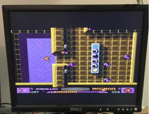
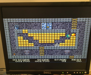
A lot of stuff works. I will note that I used the NMS-8250 ROMs (in the Omega) for most testing (including the disk rom noted above). Have a look at the screenshots below.
However, having done this sort of thing a few times you have to keep on testing
and testing … and that’s not much fun, so apologies if your favourite game or app does not work. Stuff I have tested
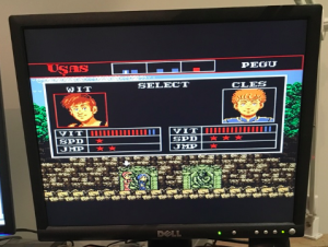
– Treasure of Usas (only the ROM version works)
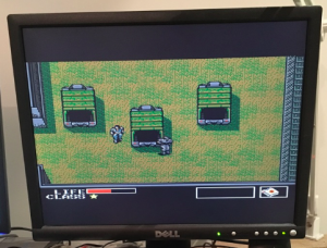
– Metal Gear (most of the dsk versions seem to always have one of the rooms garbled … which also occurs in fMSX for me. however, the ROM version works fine).
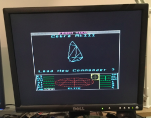
– Elite works
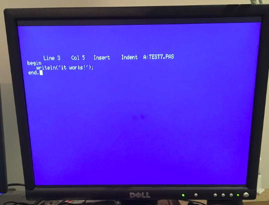
– CPM stuff seems to work (though Turbo Pascal 3.0 does not like what I do with the B: drive when you go to save). Zork works and MSX-DOS1 boots.
Saving to disk also works (ie. it writes back to the dsk image on the SD card).
Renaming the ROM files I realise is awkward. For now, I grab the latest softwaredb.xml from https://romdb.openmsx.dev/archive.php , do a sha1sum on a rom file I have, then find the sha1 in the softwaredb.xml. That will say whether its Konami (ie. .konami4) or Ascii8 or Ascii16.
Originally, I did not have the kcmfs file selector. It seems to work OK, but there might be cases where you need to power off/on the MSX computer while still having the stm32f407 powered (I’ll note here that currently all my testing is done with the stm32f407 board powered by its USB port, and just having GND connected to the MSX computer).
Unlike the other ROM emulation stuff I’ve done, I do realise it is harder to connect these cheap stm32f407 boards to a real MSX computer. In systems like the Acorn Electron and Amstrad CPC 464 the expansion connector is a simple PCB edge connector. You can just get a edge connector socket, solder some header pins to it, grab some jumper wires and then connect the stm32f407 board and test it all out. However, in MSX the edge connector socket is (usually) on the circuit board, and you would need a board with PCB edge connector fingers on it to plug in , then somehow attach header pins to run jumpers to the stm32f407 board.
Ultimately, it would be nice to design a board specifically for this …
UPDATE: 13/Sept/2020
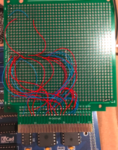
Well, I haven’t quite made a cartridge up, but I came across some designs for MSX prototype cartridges. There are two sizes. I picked the large one, sent the gerbers to a cheap Chinese PCB fab, and voila ; a sort of semi permanent cartridge ( I happen to like a maze of Kynar wires). Underneath the DevEbox STM32F407 board are some arduino style header sockets that the board plugs in to. Then you just need to wire all the pins up.
I’ve made some minor updates to the code recently as well. I’ve added in the ability to use cartridge ROMS for KonamiWithSCC. There is no SCC chip though. This is just for those cartridges that use the KonamiWithSCC banking technique and can use the PSG for sound. I added this in purely so I could play all the ported Coleco games. So you need to rename the cartridge ROM files to end in .konami5 if you want to use this format.
Source is available at https://github.com/kernelcrash/msx-rom-and-floppy-emulator .