So I am quite enjoying playing around on my new C64. Loading stuff onto it is either by using uno2iec or using real floppies. uno2iec has the major convenience of ‘you just need an arduino and some wires’, but you still need a real PC (or rPi) attached. There’s also limitations to what uno2iec can run (which is not uno2iec’s fault).
Anyway, the other big project out there is SD2IEC. I have no idea whether there is a master site anywhere for it. There are firmwares to download at sd2iec.de and the readme in the firmware downloads refers to pontoppidan.info/lars/index.php?proj=mmc2iec which has some info but doesnt look very up to date. There are ads on ebay for prebuilt SD2IEC’s but they seemed out of my price range, so I wanted to make one myself. There are a few blog posts around and lots of forum posts about people building them. I ended up following much of the 16bitdust post mainly because it actually had a few schematics (and I was struggling to find schematics anywhere). I guess I was initially confused by the fact there are multiple hardware platforms supported (larsp, sw1, sw2 etc) and I couldn’t really tell if one was better than the other. I probably shouldnt have worried too much about finding a schematic as the circuit is very very simple.
The various hardware versions seem to relate to how people have approached the whole 3.3V/5V issue; C64 is 5V logic, the microcontroller is usually 5V, but can do 3.3V and the SDCard is 3.3V. For the larsp circuit, the microcontroller runs at 5V, so it interfaces straight to the IEC port whereas voltage dividers are used for outgoing signals to the SDCard and a 3.3V regulator is used to supply the SDCard. So I had just recently made the SIO2Arduino for my Atari 800XL and effectively ‘ran the SD card at 5V’ which I didn’t realise was a ‘bad thing’. It seemed to run and I know its probably killing my SD card slowly. Anyway, I decided to do the same for my SD2IEC .. just run the SD card at +5V to test it out and then do something about the 3.3V stuff later.
As to the microcontroller, you can’t use a Atmega328p like you find in an Arduino Uno. SD2IEC requires a decent amount of flash and ram. So the main thing I needed was an Atmega1284p or 644p. I ordered a 1284p which cost maybe NZ$14. So I had an 8MHz crystal already. So now I just needed to install a firmware on it. I ended up using an Arduino Uno as the ‘programmer’ for it. So the arduino IDE comes with an example ‘sketch’ called ‘Arduino ISP’. You just program that in to an Arduino and then you can use it with avrdude to program the 1284p. The ArduinoISP page has a decent amount of info on how to do it. The main thing is the wiring to the 1284P. This maniacbug post has a bit of information on what you need to do (ie. D13 on an Uno to p8 of the 1284p, D12 on an Uno to p7 of the 1284p and so on).
I had avrdude installed in a Fedora 21 box here and plugged the Uno into that. I wasn’t 100% sure which ‘programmer’ to specify when using avrdude with the ArduinoISP, but found some suggestion to use ‘avrisp’. Anyway, I wired it all up with the 1284p on a breadboard, and the uno wired into it and also supplying +5V, and ran this;
avrdude -P /dev/ttyUSB0 -b 19200 -c avrisp -p m1284p -v
That came back with some stuff about the Fuse settings which suggested it was talking OK to the 1284p. So I grabbed the latest firmware for a ‘larsp’ with a 1284p; sd2iec-1.0.0alpha0-89-g9883eac-larsp-m1284p.bin and kicked it off to flash
avrdude -P /dev/ttyUSB0 -b 19200 -c avrisp -p m1284p \
-U flash:w:sd2iec-1.0.0alpha0-89-g9883eac-larsp-m1284p.bin:r -U lfuse:w:0xef:m
I did read a fair bit trying to work out what to set the fuse settings to. I couldn’t work out whether the high fuse or extended fuse needed changing at all. So I decided I would first try setting just the low fuse (since that one determines whether to use the internal clock or external crystal). I found a good online AVR fuse calculator for this sort of thing.
So the flashing worked, so now I just hooked up the 3 wires and GND for the IEC bus and tried powering it on. So getting back to the schematic. For my initial test I just had;
- The ATMEGA1284p on a breadboard
- the 1284p reset going to a 4k7 to +5V
- An 8MHz crystal and some related capacitors
- 100nF cap across +5 and GND
- the two LEDs and related resistors off p39 and p40
- and the power lines connected; p10 and p30 to +5, p11 and p31 to GND
- And a DIN plug hooked up to the 3 IEC lines on p22 (ATN), p23 (DATA) and p24 (CLK) and GND.
So with that setup in place, I tried the SD2IEC status check;
10 OPEN 15,8,15: INPUT#15,A$,B$,C$,D$
20 CLOSE 15
30 PRINT A$,B$,C$,D$
RUN
And I got the message with the SD2IEC version number. All good.
Next step was to wire up the SD card. So, as mentioned I just wired an SD card straight in to the ATmega1284p with no level conversion and ran it at +5V (ie. the same as the hacked microsd to SD card adapter I had used for my SIO2Arduino setup).This was purely for testing, and rather than add in some sort of 3.3V level stuff using resistor dividers and a 3.3V regulator, I just ordered some ‘Micro SD TF Card Storage Memory Module SPI Level conversion For Arduino’ adapters off ebay. Since an Arduino uno runs at 5V, these adapters are perfect. You supply +5V, and 5V logic signals and the board has a 3.3V regulator and does the level conversion. All for about $1.50.
So I just wired up CS-, DataIN, CLK, DataOUT and Vcc and GND to the SD card, then I put some C64 files on a FAT formatted 16GB micro SD and tried it out. It did not work. ‘LOAD “*”,8 would hang. I tried reformatting the micro SD on various VMs and machines. That did not work. I tried ‘LOAD “$”,8 then LIST and that showed me EEPROMFS, not the content of the SD card. Then I looked at the other lines to the SD card which include Card detect and write protect. I had not wired anything for these. After some digging I worked out I needed to tie card detect (p16 on 1284p) LOW. Once I did that and reset the 1284p I could finally see the content of the SD card. I’ve also tied the write protect low as well (I think LOW means ‘write enabled’)
And I finally got to use the SD2IEC. This futurewas8bit page has a decent intro on how to use it. A lot of the games that would not load on the uno2iec, do load on the SD2IEC (eg. Turrican or GI Joe). It seems slower than uno2iec, but that might just be perception as uno2iec has visual indications on your PC of something loading whereas the SD2IEC just has a solid LED to show its accessing the SD card.
Anyway, SD2IEC is cool. Pretty easy to hack together yourself. I originally had it on a breadboard and it worked OK (though I am starting to hate these cheap MB102 breadboards you get from China. Sure they are very cheap, but they do not like moderate frequencies at all. Bumping the 8MHz crystal often stops the whole thing working. In contrast, my 30 yr old breadboards seem to work perfectly for this sort of stuff). Anyway, I’ve since mounted it all on a small protoboard.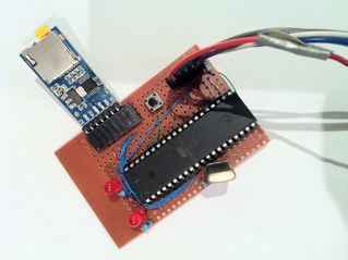 I should have used a slightly bigger board as I didn’t really end up with enough room to put two buttons (so I just have the NEXT/Diskchange button. I have a reset switch inside the C64 and use the RESET on the IEC connector to reset the Atmega). Due to the type of protoboard I used a few of the components are mounted underneath the chip inside the socket and the microsd adapter on an angle is a bit of a mistake on my part. I built the board before the microsd adapters turned up and chose to mount the socket flush against the PCB … which doesnt actually work the way the Arduino microsd adapters are made (I should have done more research). The only thing you can’t see in the picture is the wires to the IEC DIN plug … and the red wire goes to 5V on an old cassette port plug that I hacked off a C64 printer adapter.
One thing to note is that you can work out much of the wiring for the hardware variants by looking in the SD2IEC source. In src/avr you’ll find arch-config.h which has a series of IF/THENs for the various hardware ‘variants’. You’ll see ‘Larsp’ in the variant ‘3’ section. You can then see things like PA0 and PA1 are used for the LEDs, the IEC bus is PC0,PC1 and PC2, and the NEXT and PREV buttons are PA4 and PA5. The only stuff I couldnt really find is the definitions for the SD card interface.
So using SD2IEC is pretty straight forward. If you put FileBrowser on the root of the card and D64 images in directories, you can pretty much just LOAD “*”,8,1 RUN to get going. I’ve also tried SJLOAD … which sometimes seems to work well … but often not. I may have to look into JiffyDOS or similar.