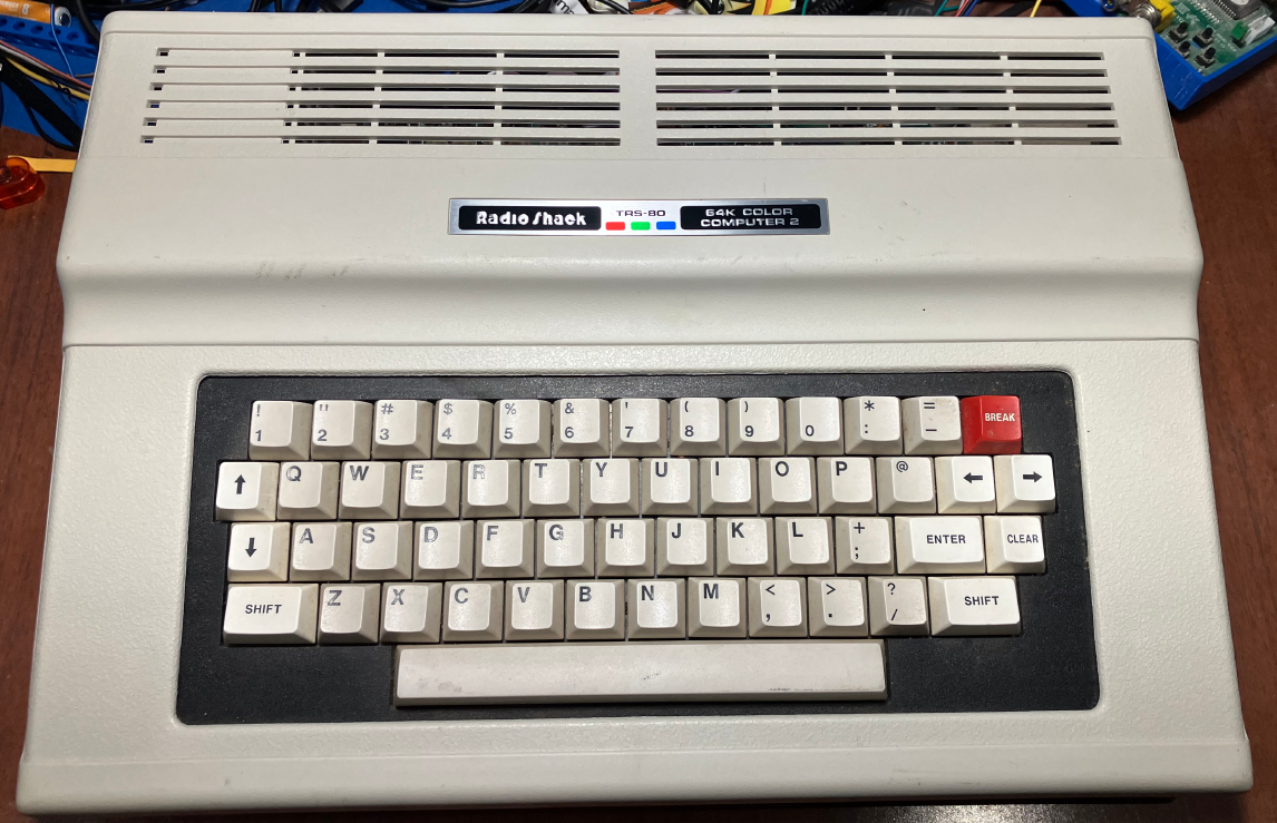
Radio Shack (or Tandy as I always knew it growing up in Australia) hopped on the home computer bandwagon quite early. There was the TRS-80 in 1977 and then in 1980 they came out with the ‘Color Computer’ (aka ‘CoCo’) . That was the Color Computer 1. I’ve always assumed it is based on a bit of a reference design from Motorola; a 6809E CPU, a 6883 address multiplexer thingee, a 6847 video chip. some dynamic RAM and a few other bits. Actually, if you look at the 6847 datasheet there is a design that looks a bit like that but has a 6846 chip in there which the CoCo never had … so I am possibly completely wrong. Anyway, thanks to a reader of this blog, I recently received a Color Computer 2. It’s an American NTSC one. I am in the PAL part of the world, and CoCo 2’s were sold in Australia at least but they produced PAL video, not NTSC. They also ran on 240VAC, not 120VAC like American ones. Originally when I received it, I thought ; I just need to hack together a power supply, do a composite mod and then work on updating my dragon-rom-and-floppy-emulator so that it works with the Coco 2.
What I found is that I have spent an enormous amount of time trying to get composite video to work well. But more on that later. First the power supply.
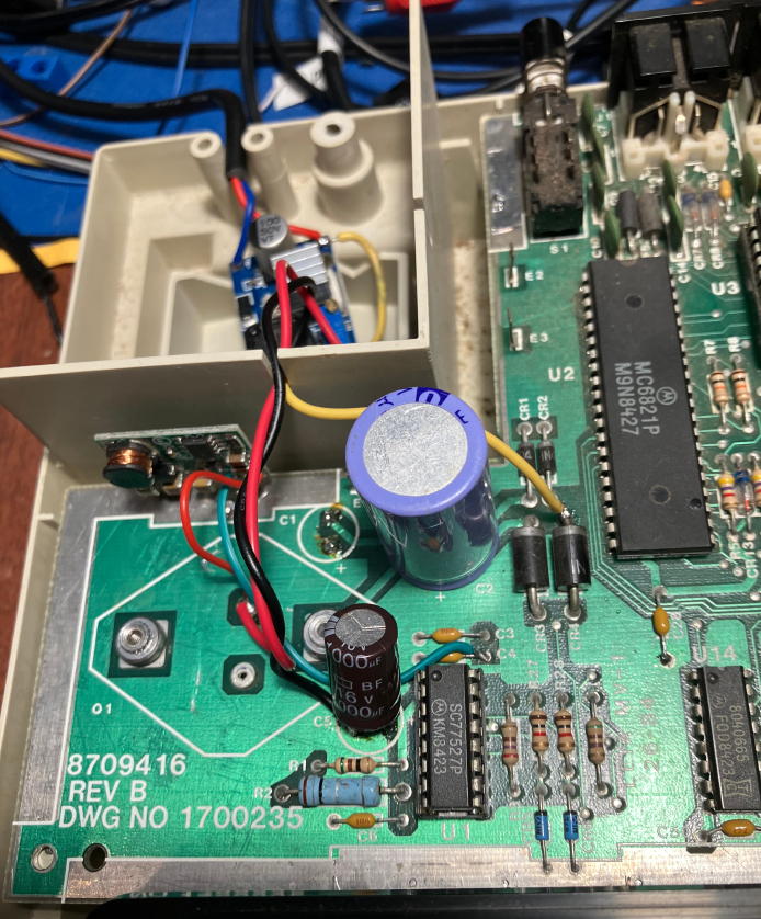
Inside the Coco 2 there is an actual 120VAC transformer. If I had a step-down transformer, I might have used that, but I don’t have one. So I decided to do much the same power supply surgery that I did to my Dragon 32. I used an LM2596 PSU to produce +5V from a +12V DC adapter. And the Coco 2 has this ‘SALT’ chip near the power supply that takes a ‘hardly regulated’ -12V, and converts it internally in the SALT chip to -5V which is then used for the RS-232 stuff and possibly the cassette stuff. So I used one of those -ve supply generation DC-DC boards again (+ve voltage in, -ve voltage out). I did not have one that could generate -12V DC. I only had a -5V generating one, but the output voltage is determine by two SMD resistors. I don’t have a vast collection of SMD resistors, but found two that would give me -9V … which I thought was ‘close enough’
I found this page on the CocoWiki about using an AT power supply to power a CoCo and used the same entry points for the different DC voltages.
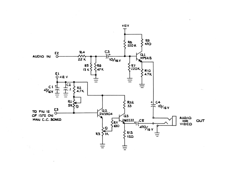
Now to composite video. The Coco 2 comes with an RF modulator designed to be connected to a 1980s American NTSC colour CRT TV. But the RF modulator is different to most I have seen before. Most other older 8 bit systems will produce composite video somewhere on their mainboard and feed that into an RF modulator box, but the Coco 2 is different. The RF modulator tin can contains an MC1372 chip (which I suspect was designed to ‘go with the 6847’). It takes the Y (luminance and sync), Phi-A and Phi-B color difference signals and produces an RF TV signal directly. But there is a way to convince the MC1372 to produce composite instead.
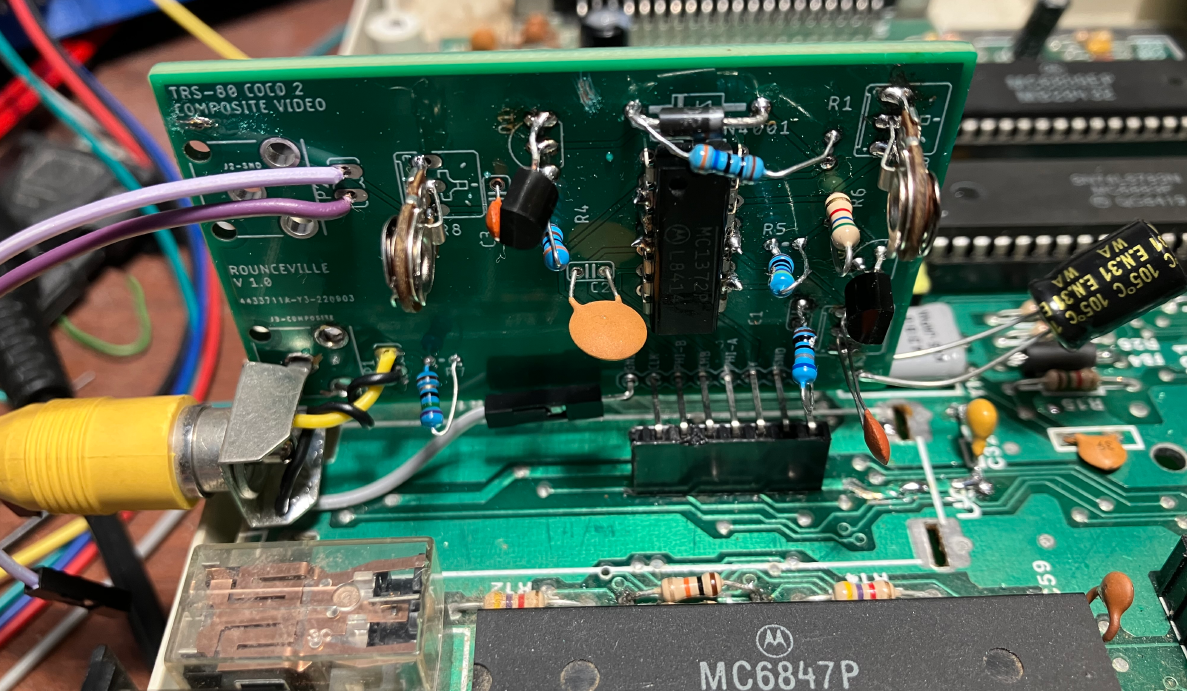
If you look at the MC1372 datasheet it has an example of using a diode and resistor across pins 13 and 14 to force it in to composite mode. Now potentially you can hack away at the circuit board inside the RF modulator tin can to do a composite mod, but the reader who had sent me the Coco 2 also sent me a PCB for a ‘composite mod’ (aka Rounceville board). This required me to desolder the RF modulator tin can which ‘takes some effort’ and also desolder the MC1372 chip (just noting there are one or two places on ebay that seem to sell this old chip). You really have to read the pdf instructions on the project page as I had a v1.0 PCB and the diode is the opposite way around (I did figure out later the diode direction decides whether the signal is inverted or not). The RCA connectors are not actually connected to anything (which as the author notes is because RCA sockets amazingly come in many different forms) so you need to solder some small wires to handle that. At the time I put it together I did not have any 1K trimpots either so I had to be inventive. Eventually I got a picture like this (apologies for the light):
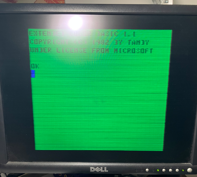
Yep, it was quite horrible. Lots of flickery horizontal black lines that danced around a lot, and if you look closely you can also see the first vertical bar of the D and B characters is very faint. I tried different resistor values where I was meant to have 1K pots but it didn’t help. Then I found this 6847 test circuit page and tried the B&W composite transistor circuit. I didn’t have the same transistors so just used BC547’s instead. That gave me a reasonably nice B&W picture, but realistically I could still see the random flickering horizontal lines, they just seemed more washed out on a nice black and white image.
Then I seemed to go on a hunt for ‘composite video circuits’. A lot of them are similar to this example from the 6847 datasheet (including the one I had built):
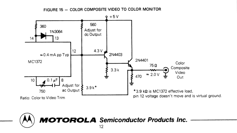
At least I now had some absolute resistor values I could try. I ended up just using 680 ohm resistors for the one between pins 8 and 10, and the one between pin 12 and +5V.
As the composite was driving me nuts, I decided to take a break and look at modifications to the dragon-rom-and-floppy-emulator to make it work with the CoCo 2. It is no secret that the Dragon is very very similar to the CoCo 1 and 2. They both have a 6809E , a 6883, a 6847, two 6821’s (though one is a 6822 in the Coco 2), and a 6 bit DAC for sound. They even have the same pinout for the cartridge connector. So that meant in theory I could just plug in my dragon-rom-and-floppy-emulator board, but put some CoCo ROMs and disks in the ‘dragon’ folder and it might ‘just work’.
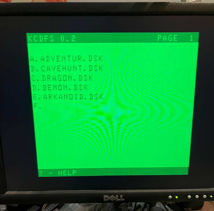
No, well not quite. First off I have a menuing system kcdfs that boots up when you first turn the Dragon on. It is quite a simple 6809 assembly program. It writes directly to bytes of screen RAM and reads the keyboard. In the CoCo the text mode screen RAM is mapped to the same location as the Dragon, so that’s too easy, but I call a ROM routine to check for a key press and the Dragon ROMs are not identical to the CoCo ROMs. One small change for getting a key and it now started up OK. Another change is how to force the CoCo to reset. Suffice to say it’s different. I now could boot into kcdfs and select a CoCo ROM and start a cartridge game!
But then the big thing was to handle disks. Here’s some details
- In the Dragon the FDC is mapped to 0xFF40-0xFF43 and there is a latch that controls a few floppy related things at 0xFF48
- In the CoCo, the FDC is mapped to 0xFF48-0xFF4B and the latch is at 0xFF40
- The bits of the latch are similar but not exactly the same.
- There is still a latch bit that enables or disables whether INTRQ generates an _NMI, but there is also a latch bit that enables/disables the DRQ from driving the _HALT line of the 6809E.
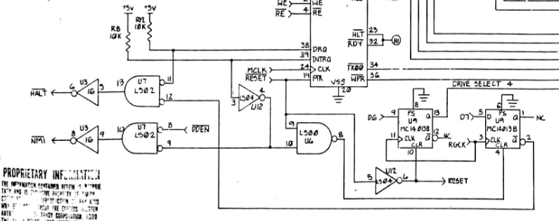
Per the Color Computer Disk System Schematic (this says its the new one … whatever that means), you have this important part below. So for _NMI, it will only go low when INTRQ goes high IF _DDEN is also low. _DDEN comes from elsewhere on the schematic (the lower 6 bits of the latch are on a 74LS174), and _DDEN is the inverse of latch bit 5. So when bit 5 of the latch is high (ie. double density enabled) , _DDEN will be low which means INTRQ can trigger _NMI’s.
_HALT potentially goes low when DRQ goes low. At first this seemed a bit weird but I realised on the 6809 side of things there must be a simple loop that reads or writes sectors by simply reading or writing the FDC data register in a tight loop and not checking anything between accesses. For example, with a read of the FDC data register, DRQ goes low after the byte is read by the 6809. ie the CPU is halted until DRQ is high again (which the FDC does when a new data byte is ready). So it unhalts when the next byte is ready, and as soon as the CPU reads the FDC data register it halts again. All this activity is first enabled by setting bit 7 of the latch (effectively the _HALT enable bit), but you’ll see INTRQ going through some gates such that when INTRQ goes low, bit 7 of the latch will be cleared , and hence disabling the ability to _HALT the CPU.
 A
AThe _HALT changes required a bit of work. The Dragon doesn’t use _HALT for it’s floppy interface, so a change is to wire PC13 through to _HALT.
Anyway, I got it to work. There’s a few more changes, as the most common disk image for Coco’s is .dsk which is just a raw single sided 35 track by 18 sectors of 256 bytes (ie. 161280 bytes long). The Dragon I found uses .vdk files that are 40 track x 18 x 256 with a small header.
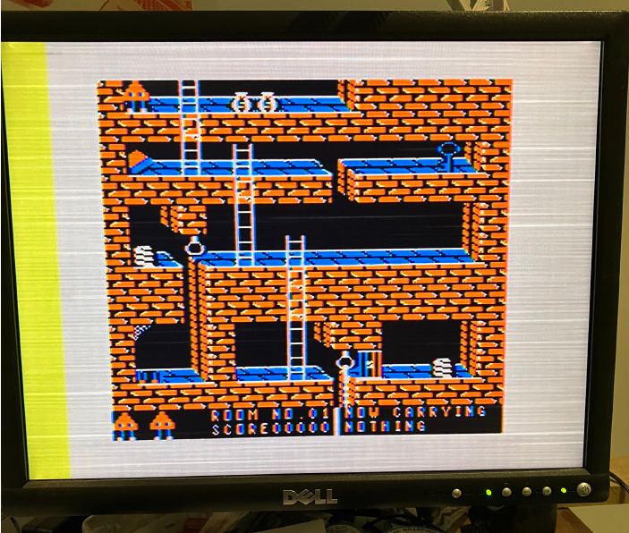
So I had seen a youtube video of someone playing ‘Dragon Slayer’ , so I loaded that using LOADM “DRAGON” and got this screen.
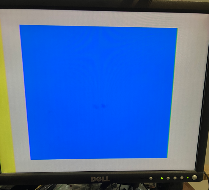
Everyone who has a Coco knows what this means, but I am completely new to this so I sat there for some minutes thinking the game must be still loading. Eventually I tracked down the Dragon Slayer manual. It says
To load the game type LOADM “DRAGON” and the program will auto-execute. You will then see a red or blue screen. Press reset until the screen turns blue. Then hit any key to continue with the game
What the?
OK, so I just hit a key and the game starts. I felt stupid. But what’s the story of this red or blue screen? … and I found other games that had the same loading methodology. You press reset a few times. I even went back to Dragon Slayer and noticed that yes occasionally I did get a red screen and if I hit a key then, the game would start, but not in orange and blue. It was green and purple or something.
Of course this is the special artifact colour modes of the CoCo. Basically some extra graphics modes that utilise a bit of a hack/feature of high resolution modes when generating a colour signal. As for the press reset thing, that was a puzzle too, until I found this (apologies. I have lost the link to where I found this).
The 256×192 two-colormode allows “artifact colors” on a NTSC TV, due to
limitations of the phase relationship between the VDG clock and colorburst
signal. In the white and black colorset, alternating dots bleed together to
give red or blue, in effect giving a 128×192 four color mode with red, black,
white, and blue. Reversing dot order reverses artifact colors. However, the
color formed is somewhat random on RESET, so many games have the player press
RESET until the colors are correct for the game. The CoCo 3 fixed this
problem, always starting the same, and holding F1 during reset would reverse
the colors. Artifacting does not work on the RGB monitors
and this
The graphics chip internally can power up on either the rising or falling edge of the clock, so the bit patterns that represent orange and blue are not predictable. Most CoCo games start with a title screen and asks the user to press the reset button until the colors are correct.
So not all games use these artifact modes. And a very important thing is that these artifact colours only work with composite video (and RF I guess too). They don’t work with S-Video or any attempt to do component video as the whole idea behind artifact colours is that its to do with the luminance signal affecting the chroma signal in a composite signal. Another important factoid is that artifact colours work a bit better with NTSC rather than PAL, hence why people in the PAL world are probably not so familiar with them. There is a wikipedia page all about composite artifact colours.
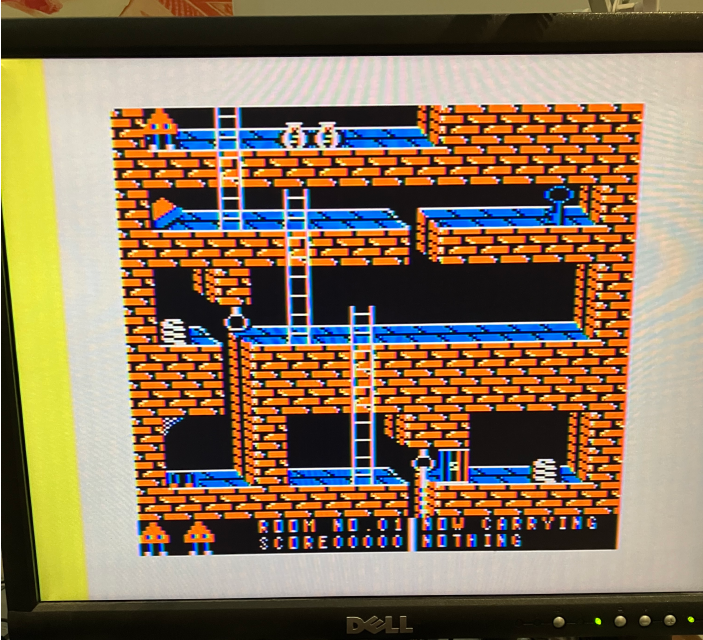
Anyway, I could get this in Dragon Slayer now
It kind of looks right but I still have lots of flickering horizontal lines, and what’s with that yellow thing on the left?
So I started thinking about the power supply. These cheap DC-DC supplies, being switch-modes do generate a lot of ‘noise’. Noise that the Coco (and Dragon that is very similar) were probably never designed for. So I started re-capping many of the electrolytic capacitors to see if that made a difference. I started at the left of the board. There are two caps underneath the board ; C5 and C1. C5 is across the +5V, and C1 is across the -12V (or -9V in my case). I replaced those with more modern low ESR caps. No change in the composite quality. I replaced C62 (near where the RF modulator goes) with a similar spec cap. No change. And then I replaced C11. It is meant to be a 100uF, but I thought this right hand side of the board is so far away from where the power comes in that it really needs a beefier cap. So I put a 1800uF low ESR cap in there, and voila. Most of my flickering horrible horizontal lines were gone. It was still a long way from perfect, but was a lot lot better (NB: I worked out later that simply removing C11 fixed a lot of my flickering horizontal lines, so it may just have been that my original C11 was faulty).
I still had the yellow bar. I did find this zippsterzone post about the yellow bar. It talks about some sort of failure in the ‘artifact circuitry’. By now I had spent a lot of time staring at the Coco 2 Service Manual for my model. There is a bit of an explanation on page 34 about the 555 timer that sort of activates this artifact mode
The artifacting circuit in the Color Computer 2 forces the
Motorola MC1372 (09) to generate the burst signal in the
high resolution mode, contrary to the original design of the
component. In addition, the phase of burst generated is
controlled to a limited degree in order to produce a desired
set of hues, or tints, from the black and white signal which
is now being interpreted as color.
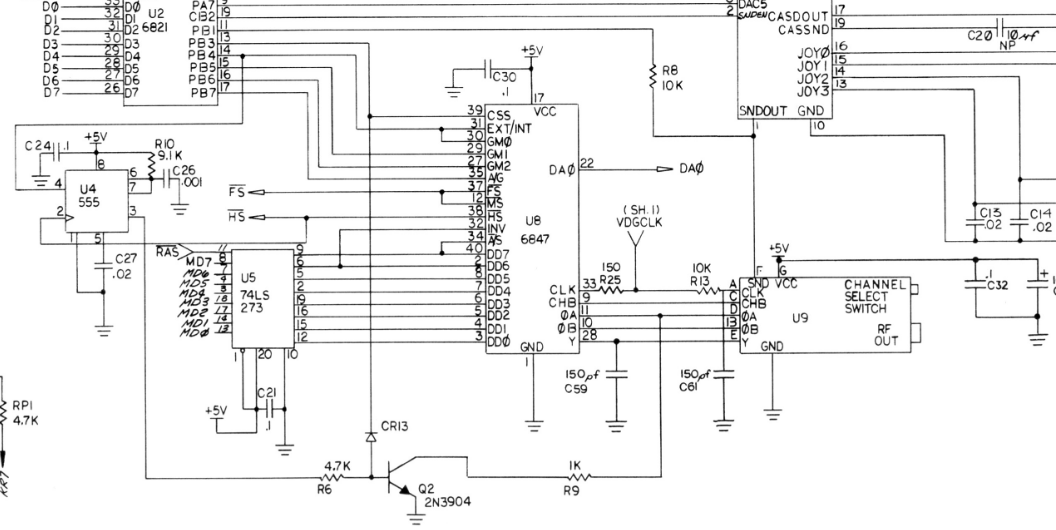
So this 555 timer effectively does a one shot at the appropriate moment sometime around the horizontal sync pulse. You can see how it’s wired up in this snippet of the schematic:
There are actually some really good videos on youtube showing how this is meant to work on an oscilloscope and so on. But anyway, apparently this 555 timer circuit can easily get ‘out of whack’ by a capacitor drifting in value over 40yrs, or some other component in that area failing. I changed C26 to a 680pF but there was no change in the yellow bar, so I left that one for another day.
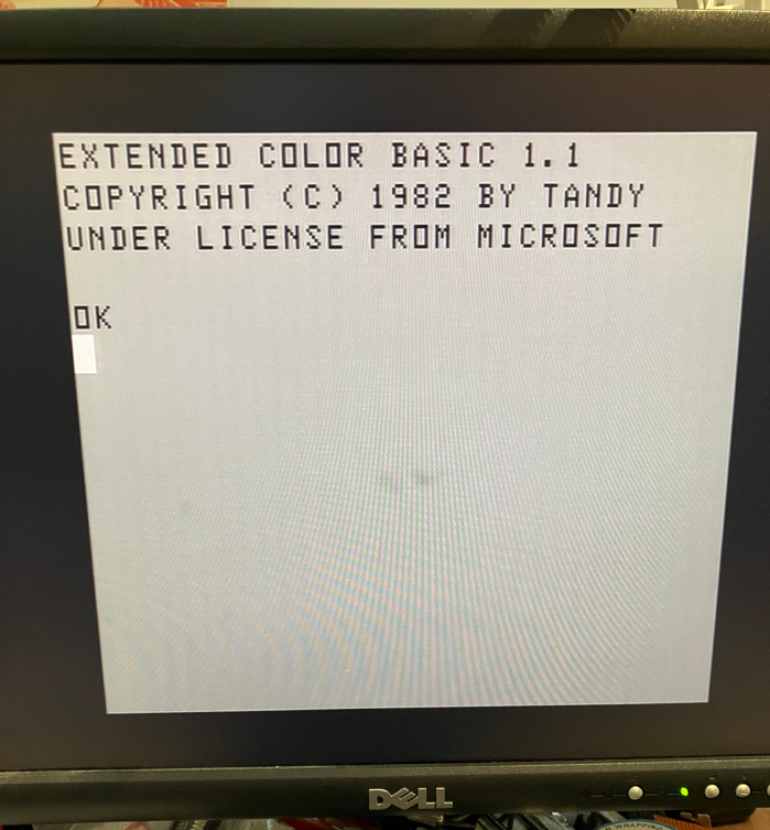
So I had better composite video but it was still not amazing. One thing that really puzzled me was that the green text screen at turn on was in one of two states
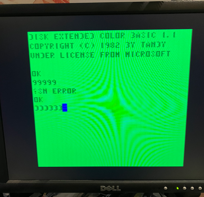
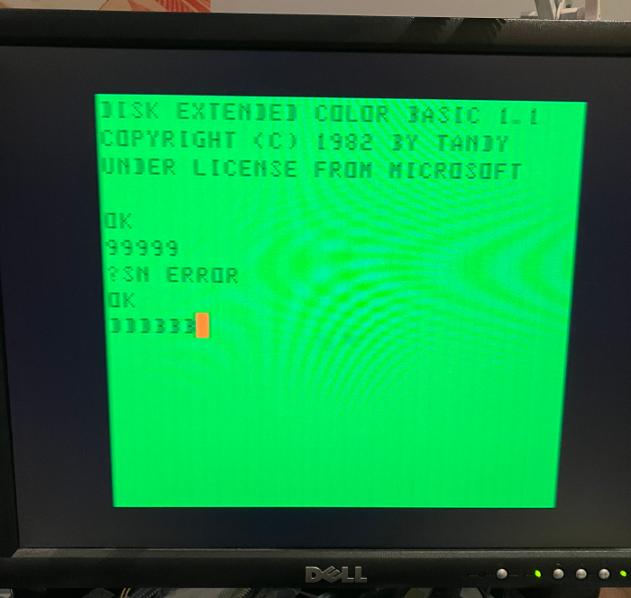
The state on the left is what I call ‘the better state’ in that the font is darker and sharper, but the first vertical bar of the D and B characters is missing or very faint. And the ‘state’ on the right you can see the first vertical bar of the D and B characters (‘just’), but overall the picture is not as sharp and is a bit fuzzier. I kind of think the two states must relate to whether the video chip is starting up on the positive or negative edge per the discussion on artifact colours.
I then went on a hunt to try to improve the ‘state’ on the left. I wanted my D and B characters. So I tried a heap of different composite circuits. I tried component into a GBS-8200 using info from this stardot post. but the black level was a bit broken as the image was always blue-ish and I could not figure out how to fix it. The component output was very nice though. I found this great long youtube video about various composite and s-video mods. I tried the S-video from that post, or a slight variation of it. Essentially I disconnected the resistor in the resistor/capacitor circuit between pins 8 and 10 of the MC1372. Once you do that you get a really nice black and white composite:
And then I used another transistor and 470 and 75 ohm resistor off pin 8 of the MC1372 to generate the S-Video Chroma signal. And now my green text screens were really quite sharp
But now when I ran Dragon Slayer I got this in S-Video. ie.a black and white hi-res picture … which now having read a lot about artifact colours made perfect sense. i.e it’s meant to look like that in s-video because the mixing of the luminance and chroma signals to produce the ‘other colours’ simply does not take place in s-video. It was still a very crisp image though.
So, in terms of being able to ‘run anything’ I probably still needed to figure out better composite. I kept looking at that really long youtube video by ACs 8 bit zone. Around the 1hr mark in that video is a test shot of a Coco 2 with his composite mod and it actually has very faint vertical bars on the D and B characters … so maybe what I was seeing is actually almost ‘normal’ in Coco land. If I had an NTSC colour CRT that would be a fantastic test to see whether a lot of my issues are purely to do with modern LCD tech trying to interpret artifact colours. I notice a lot of youtubers doing Coco videos tend to use a CRT (I’ll note that all the photos on this page are of a Dell 2001FP direct on it’s composite input. I also have some other ways of plugging composite in to a monitor, but I find the 2001FP is usually the best of all options).
So the reader that sent me the Coco 2 and composite board also found the +12V composite mod that is floating around the net (which I eventually located here and here). So I built this on a breadboard behind my CoCo 2 and I worked out that it requires that diode to be ‘the other way around’ between pins 13 and 14 of the MC1372 (ie. the anode needs to connect to pin 13. The cathode to 14, and the resistor is pulling up to +5 on pin 13). The composite output was OK (though it did not solve my D and B problem), but for whatever reasons I went back to hacking at the Rounceville PCB because ‘I had the PCB’ and I really want to put it in the RF tin can at some point and eventually put the lid on this computer. I do remember thinking the adjustable trimpots ‘actually affected the video output’, whereas I find that just having the 680 ohm resistors on the Rounceville board is ‘as good as it gets’ for me.
There are in fact loads of composite circuits floating around. I probably need to try some more but I am leaning towards ‘this computer was made for CRTs’ and it’s just really hard trying to get amazing video output out of it. I’ll note some other stuff I have tried
– disconnected R9. No change
– disconnected C59. No real change
– disconnected C61. No real change
– Changed R13 from 10K to 1K. No real change
– shorted R13. That actually does make a change. For me the verticals of the D’s and B’s are visible but the image in general is blurrier.
– tried running the VDG clock direct from the 6883 via a twisted with GND wire directly to the MC1372. No real change.
The other really strange thing that has happened now after changing the caps on the board is that its much harder to press reset to get the alternate colour set. Usually I have to turn the power on and off to have any chance of getting the other colour set. Maybe once or twice I have seen the colour set switch after pressing reset for a very long time.
I’ll just note after playing around for a week or two now that the main thing that improves the composite video quality with my DC-DC power supply setup is simply ‘a really big electrolytic for C5’ where the +5V enters the board. I have two 1000uF electrolytics in parallel for C5 (I could not find a 2200uF anywhere in my junk box) and C11 and C46 (near the 6809E and 6883) as 1000uF electrolytics. They improve things ‘a little’ I think. Like I said earlier ‘I thought upping C11 was the magic fix, but in hindsight I’d say the original C11 wasn’t working well’. I’ve also had a go at using various inductors and using ‘pi filters’ to try to improve things … but my attempts have all been failures so far.
One possibility for me is to use the Coco 2 in S-video mode mainly ,and to use a simple 470pF ‘joiner’ to produce composite if I want to play an artifact game. When I produce composite that way I do get artifact colours, but seemingly only the purple/green set. I don’t seem to be able to get it into the red/orange mode. I have no idea why so for now I have gone back to composite with my funny D’s and B’s. My very tortured Rounceville board looks like this:
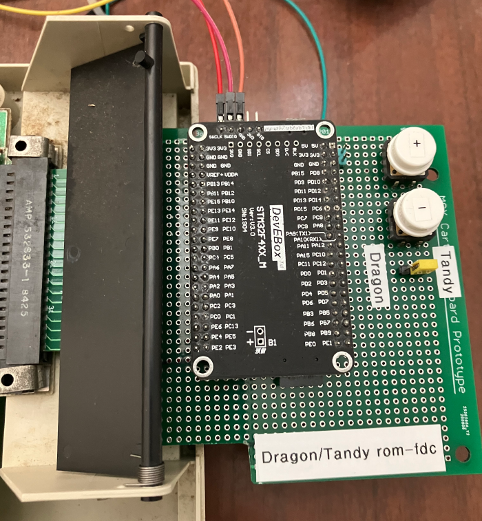
I’ve also spent some time making a single firmware for the dragon-rom-and-floppy-emulator that works on both the Dragon or Coco (I am thinking only a Coco 1 and 2 works). I’ve added a jumper connected to PA4 on the stm32f407 board. If PA4 is low on startup, the firmware assumes it’s plugged into a Coco. If its disconnected or high, then it assumes it’s connected to a Dragon. The kcdfs menu program has been changed such that it first ‘asks’ the stm32f407 board what that jumper is set to. Hence kcdfs can use the correct Getkey and Reset routines. And the rest of the code changes it’s behaviour based on that jumper. In dragon mode it still looks for a DOS rom called dragondos.rom and a directory called ‘dragon’ in the root of the SD card. In tandy mode it looks for a DOS rom called tandydos.rom (I have tested with RS-DOS 1.1) and a directory called ‘tandy’. This way I can use the one board and one SD card with either the Dragon or Coco.
And I did solve the yellow bar problem. Amazingly, replacing the 555 fixed it.
As I write this I am still testing the code changes, so it’s just in the TIM-dragon-coco-mode-version branch. TIM is because it uses some different interrupt logic incorporating a timer which I’ve been working on for a while plus it has the changes to work on both the Dragon and Coco.
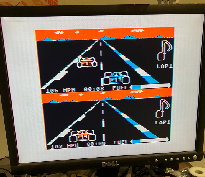
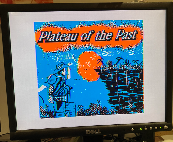
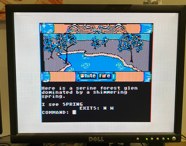
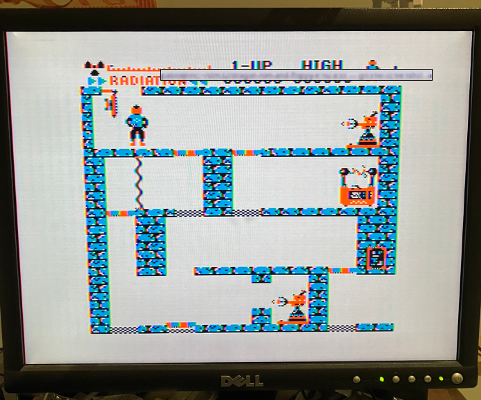
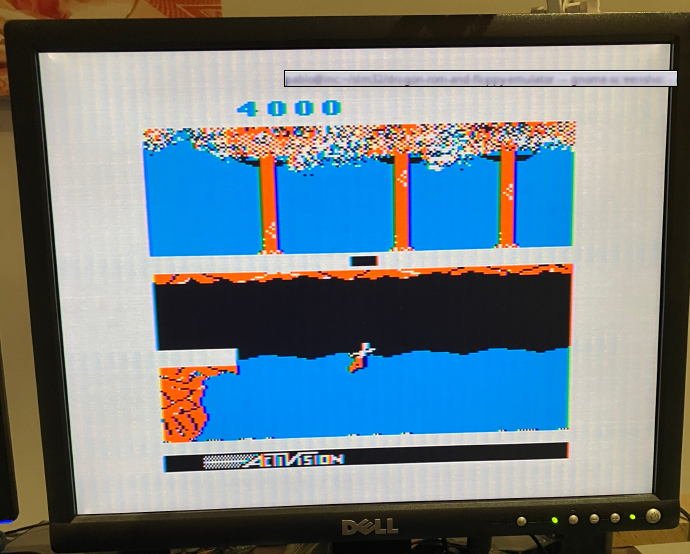
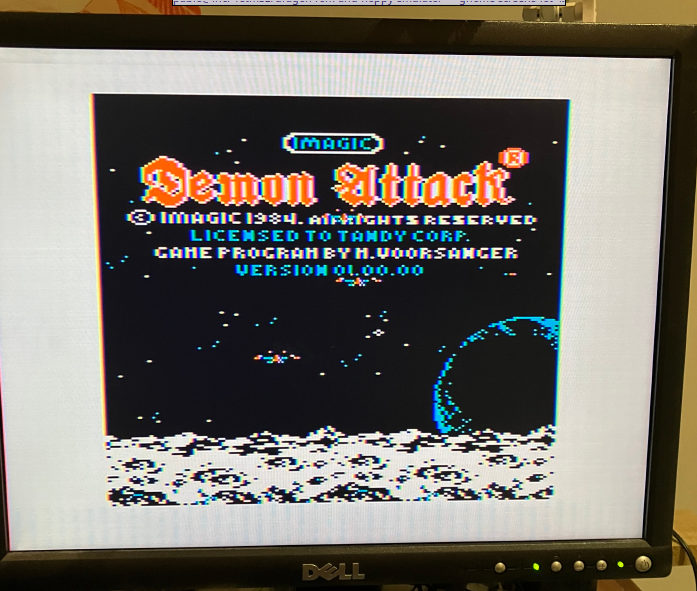
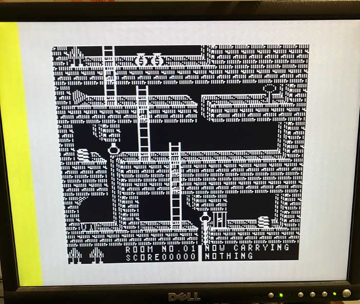
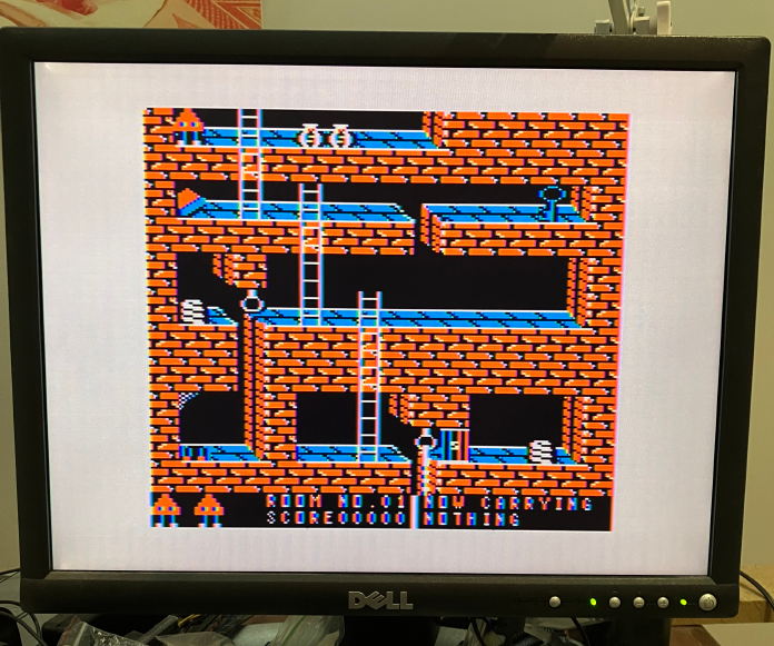
Here’s some obligatory screenshots of some games loaded via the dragon-rom-and-floppy-emulator on the Coco2. So far most stuff works, but I will note I can’t get OS-9 to work at the moment (UPDATE: I did get OS-9 and NitrOS-9 eventually to work).