So with my Funvision and Colecovision projects I tended to use a big 512K flash ROM (eg. Am29F040) to store multiple game images that I could toggle between. I have a Willem programmer to program it, and ultimately it’s pretty quick to program it, swap it in to the breadboard and try something else. But I was thinking about people who want to attempt to build these sorts of computers … and most people will not have an EPROM programmer or flash ROM programmer. One alternative I suggested earlier was to use one of the Dallas Semi battery backed RAMs with an Arduino Uno based programmer. That works, but I always wondered how hard it would be to adapt that Arduino code to program a flash ROM.
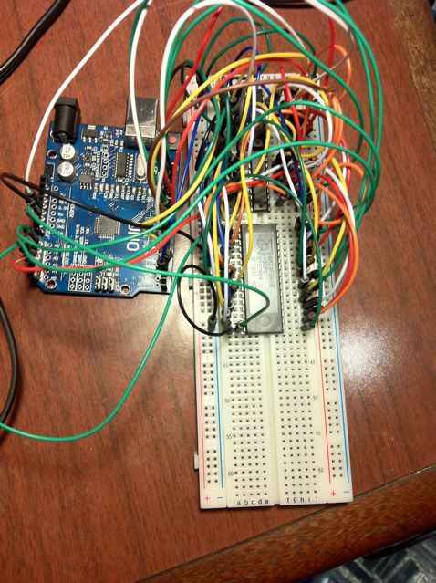
And well, that’s what I’ve done. So it’s based loosely on the meeprommer code. For the static RAM programmer I combined an Arduino Uno with a 4040 counter. Using a counter won’t really cut it for flash programing, so I am using two 74LS374’s and an Arduino Uno (I still haven’t bought the obligaory 74HC595’s). You could use LS273’s or even 373’s if you changed the code a bit.
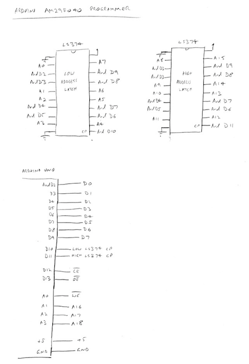
So the basic deal is that D2 to D9 on the Arduino connect to D0 to D7 of the flash ROM, but they’re also used as the 8 inputs to the two LS374’s so that we can latch a low address (A0 to A7 of the flash ROM), and a high address (A8 to A15) of the flash ROM. The other higher address lines of the flash ROM come from the Arduino’s A1 to A3. There’s just a few other pins connected directly from the Arduino.
I’d always thought that flash programming is a bit complicated and had never tried it, but it wasn’t that hard in the end. I’ve only hacked the code to program a Am29F040. I’ll leave it to the reader to adapt the code to other flash ROMs (NB: I have also tried a MX29F002 and even though I have not updated the code to identify that chip, it does indeed erase and read and write just fine. I tried an SST29EE010 and while I could read it, the identify and erase/write stuff never worked).
So, the way to use it is to write the sketch into the arduino (you will need to read the notes in the source, and some of my earlier articles about using 256byte serial buffers), then shut down the IDE and load up a proper terminal program. I used minicom (@ 115200). You’ll get a ‘%’ prompt. It should give you a blurb about some basic commands. Note that I’ve enforced the use of 5 digit hex numbers since we’re aiming to program a 512K part. First thing to try is the ‘i’ identify command. It can only detect a Am29F040. If you were going to modify the code for a different flash ROM, I would look at the code for the ‘identify’ as a starting point. Get that to work reliably identifying your flash ROM, and then the bits to chip erase and programming should be reasonably straightforward.
Next is the ‘e’ erase command. Flash ROMs tend to have a few different erase options, but I’ve only implement the ‘erase whole chip’ option. It is pretty quick.
You can read from the ROM with the ‘r’ command (eg. r 00000 or r 00000 00100).
But the main one is the write command. To write to the beginning of the flash ROM;
w 00000
You then need to tell your terminal program to send a file via XMODEM (in minicom you press ctrl-a then s, then choose xmodem). It will then transfer and program the chip on the fly. It’s slower than my Willem programmer, but its more limited by the 115200 transfer rate. It’s not too bad, and I find myself using it instead of the Willem simply because to use the Willem I have to pull out an old laptop with a parallel port to use it.
And here’s the arduino code; meeprommer-am29f040-0.01.tar.gz