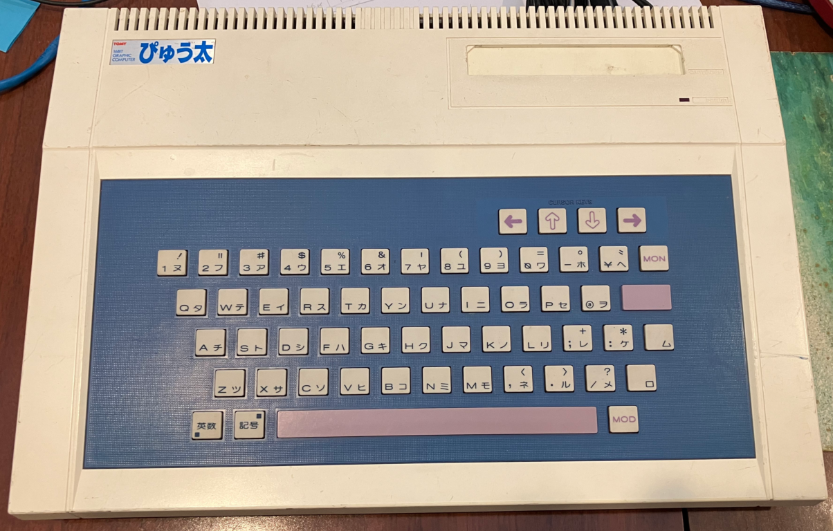
The Tomy Tutor is a not very well known early home computer (circa 1982). It originally came out as the Tomy Pyuuta in Japan (I’ve seen it written as Pyuta and Puuta and Pyūta as well). I had not heard of it myself until recently either. Doing all that research for the TI-99/4a meant I discovered a whole history related to the TMS9900 CPU and related CPUs that followed. Two interesting ones are the TMS9995 and TMS99105. The TMS9995 was meant to end up in the unreleased TI99/8. But it did end up in the Tomy Pyuuta, the Geneve and the Powertran Cortex. It is meant to be a fair bit faster than the TMS9900, so I was curious. Originally I just bought a TMS9995 off ebay, thinking I might make up a Mini Cortex . But my recent purchase of the Panasonic FS-A1 had me poking around Japanese auction websites … and hey there was a Tomy Pyuuta for sale.
This one came with a strange white box at the rear that suggested you could plug it into a modern VGA monitor. There were no markings on this box, and no amount of searching the internet could tell me what it was. Anyway, I bought the Tomy Pyuuta and mystery adapter. I was a little miffed that I did not get the special disc controllers for the Pyuuta. These are meant to be quite awful, and I was really keen to see just how awful they are.
This one is in really good condition. One thing I’ve really liked so far about buying old computers from Japan is that the ads for the computers often show the computer fully working, and often say things like “all the keys on the keyboard work”. On ebay, you are lucky if the ad says “I noticed the red power LED come on”.
I immediately pulled the strange white box apart as well.
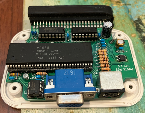
Yeah, it’s essentially a complete replacement of the internal VDP circuitry that plugs into the expansion port. That’s a fully socketed V9958 there. It is basically driving RGB out the VGA socket mostly directly. The LM1881 is there to help out with the svideo output. There’s a 138 and 139 towards the edge connector, and underneath the board is a SMD DRAM chip. Interestingly the spelling on the PCB is ‘PUUTA’. I have tried searching for information about this PUUTA RGB board, but it’s 2023, and search engines aren’t exactly designed to find what you want anymore. Hopefully I’ll eventually find some more info about it. It’s a very cool little board.
I’ll backtrack a bit and go over the technical spec of the Pyuuta. Being relatively unpopular, there is not a lot of technical detail out there about the Pyuuta. But two excellent sites are the Floodgap Tomy pages and Enri’s pages on the Pyuuta (I often have to hit archive.org if the original site is not working)
- TMS9995 CPU at 10.738MHz (ie the VDP clock frequency)
- 32K system ROM. In the Pyuuta this includes the built in G-BASIC. In the USA Tomy Tutor there is another 16K ROM as well as the 32K one.
- The only CPU RAM is the 256 bytes internal to the TMS9995
- TMS9918A VDP with 16K of DRAM in eight 4116’s. Interestingly the interrupt output of the 9918 is not connected anywhere.
- 76489 sound chip
- some related TTL logic.
- cartridge slot on top
- expansion slot at the rear
- DB9 controller port. It’s not an Atari pinout. It’s not even the TI-99/4a pinout. Its yet another pinout. It’s similar to the TI one though in that two controllers connect to it.
- RF out and composite (NTSC) and audio
- Cassette interface.
It’s quite simple, and Tomy came out with a sort of keyboard-less console version called the Pyuuta Jr. It has even less parts … and is probably a good candidate to make on a breadboard.
The 76489 is directly on the data bus, and wait states are inserted when accessing it. Everything else doesn’t incur wait states.
One interesting thing about the address decoding logic is that disable signals are exposed on the expansion connector. ie. it means you can have an external device that disables the internal 32K rom, and replaces it with its own, and also you can disable peripherals such as the VDP. Originally I assumed that that is how the PUUTA RGB works, but (as you’ll see below) both the composite and RGB outputs are working at the same time. My assumption now is that VDP writes go to both the 9918 and 9958 but reads only come from one of them.
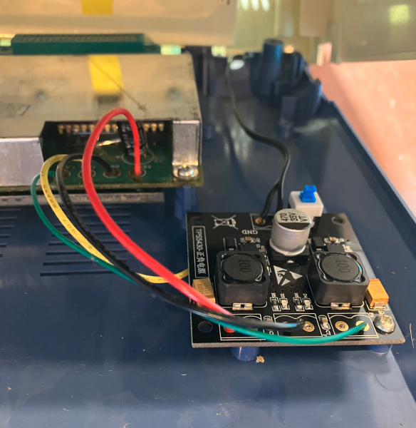
So problem number one is the power supply. It comes with an internal 100VAC switch mode that produces +5, +12 and -5. I wasn’t going to use a down converter, but I decided to use the same TPS5430 converter I had used on my TI-99/4a. They are just a cool little DC-DC board that produces +5 and -5 in my case … and I thought I’d just feed the +12 directly from the 12V DC plug pack.
Pulling apart the Pyuuta was easy, but the main snag I had was with the membrane connector for the keyboard. I saw a recent ‘8 bit guy’ video that featured the Tomy Tutor and he seems to dislike these connectors as much as I do. Rather than the membrane connector falling out, in my one it was wedged very securely in … and instead of wrestling with it to try to get it out, I ended up doing various contortionist acts so that I could leave it connected while working on it.
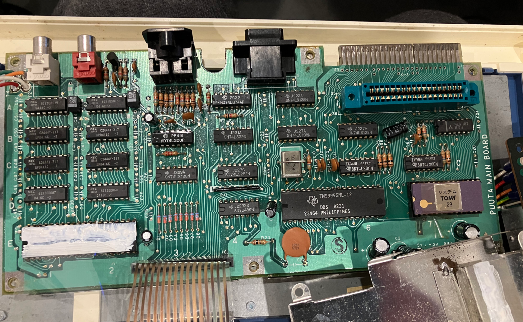
The TMS9918A is under all the heatsink goop. Don’t touch that stuff!
The 4 power wires enter at the lower right (just noting it’s spelt PUUTA again).
Here’s the TPS5430 board essentially where the old switchmode was. I just have one screw attaching it.
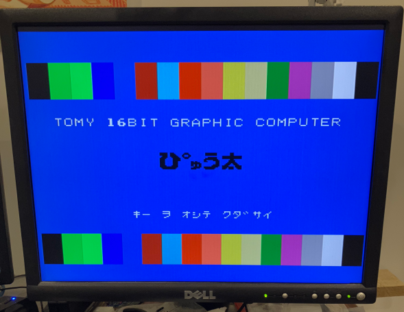
And finally I had a working Tomy Pyuuta.
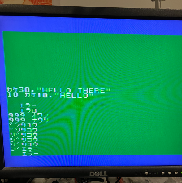
One thing I was at least partially aware of before turning it on (thanks to the floodgap site) is that you program this thing in Japanese. With MSX computers, even Japanese ones you are generally programming them in English in BASIC. Not so with the Pyuuta. It is most definitely “Japanese first”. I later discovered this really cool post from the leadedsolder site on the Pyuuta . There are notes there re the efforts to type in a G-BASIC program in Japanese. I must admit I have tried … and failed a lot … and I am still failing … so I have nothing useful to add here on typing in G-BASIC program in Japanese for native English speakers.
Of course I had to try this PUUTA RGB thing now. And gosh, its just like an MSX2 machine in terms of quality output (no surprise really). Of course it’s not VGA output. It’s just RGB output conveniently in the form of a VGA connector. Just like with the Omega MSX2 and FS-A1, I just run the RGB output into my GBS-8200 with my kinda sorta shmups mod.
So given my efforts with G-BASIC weren’t going so well, I obviously thought ‘create a ROM emulator using an stm32f407 board’. Well, I did actually think ‘whats the point?’. There aren’t a great deal of games for the Pyuuta, so you almost may as well just get a large flash ROM and a dip switch. But, I thought given I had already worked out some of the weirdness of the TMS9900 bus cycle, it should be easy to do a ROM emulator for the Pyuuta.
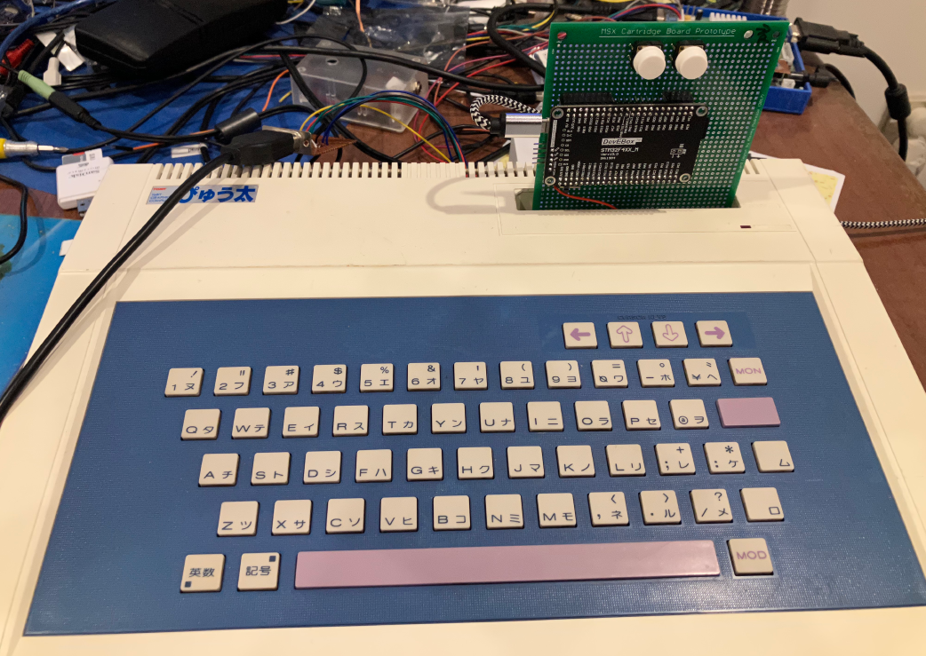
So basically the pyuuta-tutor-rom-emulator , is the ti994a-rom-grom-ram-and-floppy-emulator with the majority of features removed. There’s no RAM emulation, there’s no FDC emulator, there’s no GROM emulation, and I’ve even removed the menu interface stuff since there really isn’t a lot of games for this thing. Basically you just cycle through the rom images using the NEXT and PREV buttons. I also opted to use the top cartridge slot, rather than the expansion slot. This currently has the ramification that you can only play the 8K and 16K games, not the 32K (aka 3D) games. There’s not many of those fortunately. Use of the cartridge slot was at least partially motivated by me wanting to use this PUUTA RGB interface on the expansion connector. It’s probably not hard to rework this project to use the expansion connector and hence support the 3D games. Knowing me I will come back and do exactly that some day.
I’m not 100% sure of the differences re the 32K games. But there is a schematic of one of these cartridges on Enri’s pages (in the Pyuuta Jr page) that gives most of the hints. The floodgap pages also have a bit more background on these 3D games and the special expansion device you needed to run them on a Pyuuta or Tutor.
So does it work?
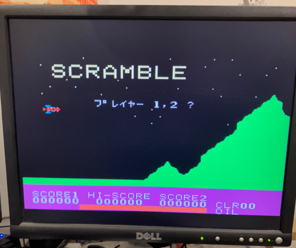
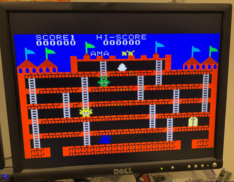
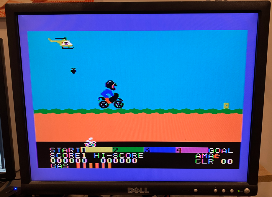
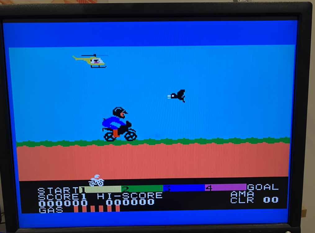
So, most of those screenshots were taken with the PUUTA RGB producing the output. It looks so good it almost looks like I am cheating. Here’s an example of the motorbike game in both composite (on the left) and RGB output (on the right):
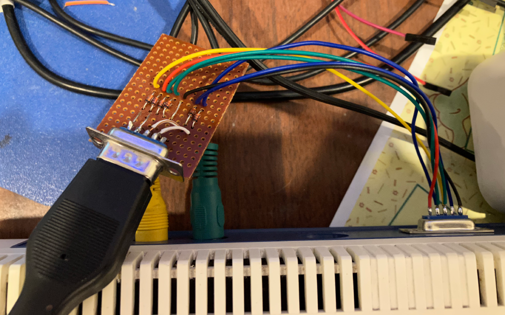
I actually got the ROM emulator thing working before I had a way to use a joystick. I’ve just made up this little gadget that lets me plug in one Atari joystick.
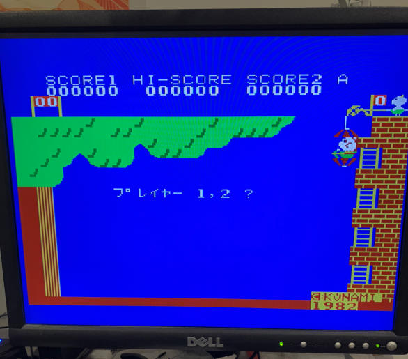
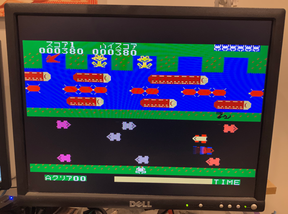
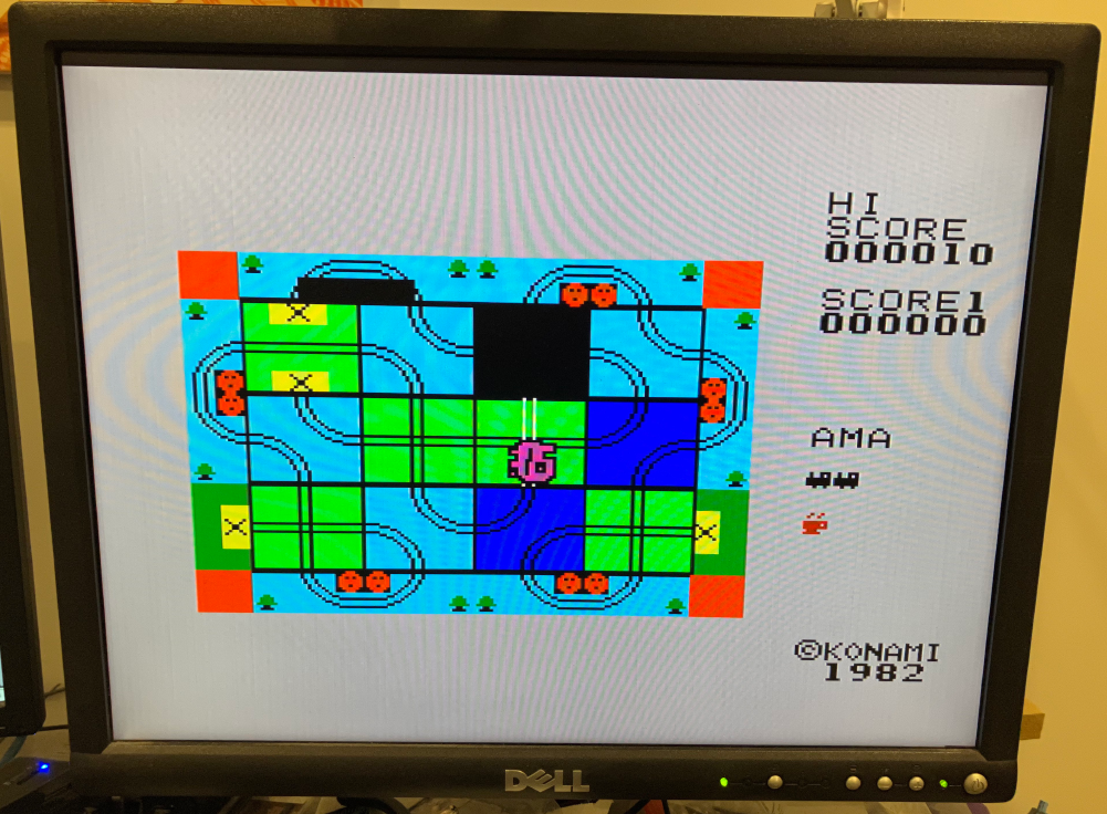
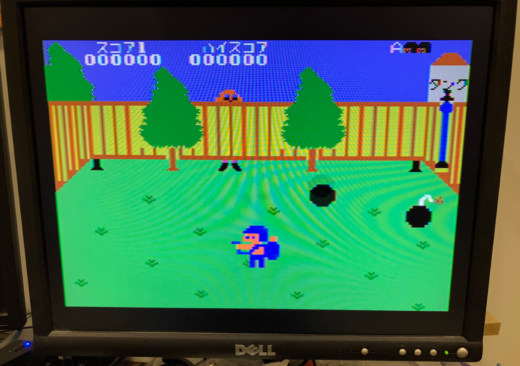
So what are the games like? Well, let’s just say they don’t really show off the TMS9995 very well. Some are quite cute/interesting though. I quite like the one where you are a cave man and go around hitting things. And the BombMan one where you try to use water to put out the fuses of bombs. Some are very very fast; Tron and that one in the submarine (well it looks like a submarine).