Yeah, it’s another MSX computer. Well MSX2 in fact. I already have an Omega MSX2, and my breadboard MSX computer is kinda an MSX1 computer, so why do I need another one? I’ve had a couple of queries recently about the msx-rom-and-floppy-emulator , and while it works fine on my Omega MSX2, I’ve had a few people mention that it partially works on ‘some real MSX1 or MSX2 systems’ and curiousity got the better of me, so I ended up buying a Panasonic FS-A1 (and no it does not come with a raspberry pi mouse)
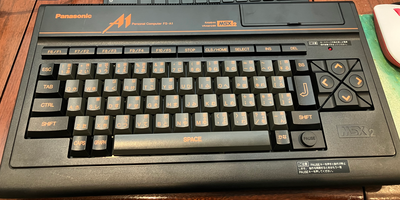
This one is amazingly clean for a 36 year old computer. It has a few ‘scuff marks’ and not much else. Even between the keys is really clean. Almost like someone had used it a few times, then put it back in the box for a few decades. Old MSX computers are not very common in NZ where I am, so that often leaves ebay as the main option, but then I thought “I should try one of those Japanese forwarding companies since there must be lots of second hand MSX computers on Japanese auction sites”. So I did. There are a few of these forwarding companies that allow you to effectively bid or ‘buy now’ something off any of the popular Japanese auction sites. I picked one forwarder based on some random user comment on reddit. I won’t name which one, but they were very efficient. I had done a ‘buy now’ on this FS-A1, and had it delivered to NZ in less than a week. For the forwarder I used, you initially pay a fee for winning an auction in Japan, plus perhaps a small domestic postage fee to get the item to their warehouse in Japan. Then there is a 2nd charge for the ‘wrap it and send it to NZ’. Of course you can only ‘guess’ what that 2nd charge will be based on the size and weight of the item (my forwarder had a ‘calculator to help you guess). I resigned myself into assuming ‘it would be more than what I thought’ and “it was!” 😉 . In the end the total cost to get the FS_A1 was probably close to what it would have been if I had bought the ‘cheapest FS-A1 on ebay’.
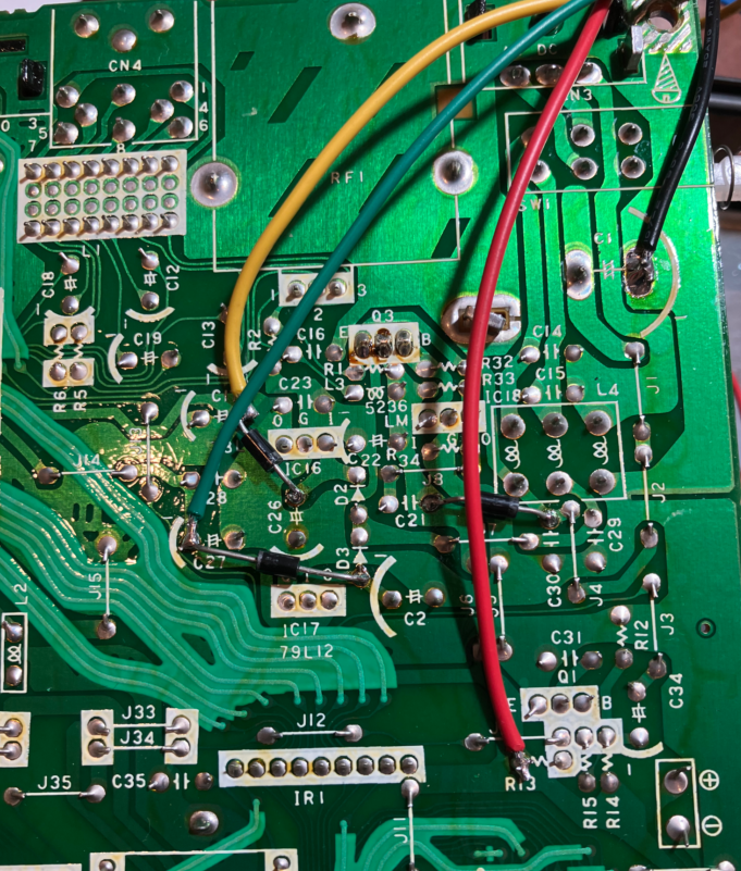
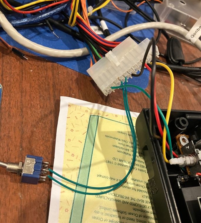
This one came with the 100VAC plugpack, which is apparently rare. It’s somewhat useless in 240VAC land where I am. So first thing was trying to work out ‘power’. I found a thread on msx.org about feeding in the required DC voltages from an alternate source without removing any components. Essentially it’s ‘add 3 diodes’ and then run some wires to a connector where you can feed in +5V, +12V and -12V directly. Ideally I could use some of these DC-DC adapters off ebay/aliexpress, but I didn’t have any spare positive to negative generating ones (for the -12V), so I opted to run some wires to an ATX connector and just use an external ATX PSU for now. It’s basically temporary, hence I am leaving the top cover off for now.
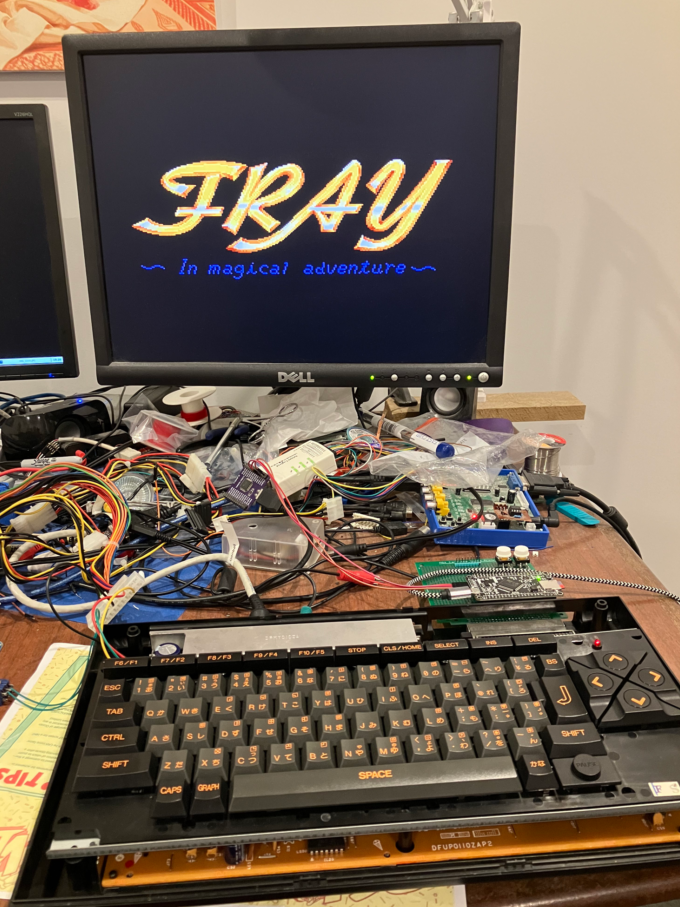
And finally I could turn it on:
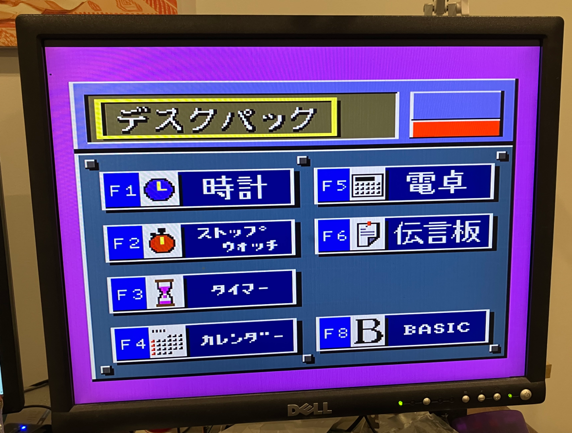
Yeah, it doesn’t auto boot to BASIC. It generally comes up in this ‘Deskpac’ thing and generally you are pressing F8.
So, the Omega MSX2 has really nice clean RGB output. The FS-A1 is really good too. I am using the same setup I had with the Omega. I am sending the RGB to a GBS-8200 with my own shmups like mod.
And so I could finally test my msx-rom-and-floppy emulator thing and hey it was failing much like these recent queries about it. Essentially cartridge emulation was working, but disk access was not working or might occasionally work.
Anyway, I went in to ‘try lots of stuff’ mode. I’ve been doing these hardware emulation things for quite a while now such that you start to get a ‘feel’ for what might be wrong. A few late nights later, and it seems to be working reliably on the FS-A1 (though I’ve since had one report of it not working on someone’s FS-A1, so maybe this is not the end of it).
- I’ve enabled the stm32f4 pullups on all the IO pins (ie. the address bus pins, data bus pins and all the control pins).
- One of the main differences between emulating ROMs and emulating the floppy disk controller and disk images is all the additional write activity for the floppy related stuff. When emulating ROMs, the writes from the Z80A are made to bank switch the cartridge. But for the floppy emulation, you have to write to all the floppy disk controller registers to do anything. I’ll note more on this further down, but during a Z80 memory cycle where it’s a write, the data to be written becomes available later in the bus cycle (ie. its not available at the very beginning). I never wait until the end of a write cycle, so I always use some delays to ‘pick a good time’ to read the databus later in the cycle. I’d added these delays for the logic to do with the ROM emulation, but I had been a little inconsistent with the FDC related delays. So I’ve made sure these ‘delays’ occur for all writes
- As the code interrupts the stm32f4 on every _MREQ coming from the Z80A, there is often a certain way to exit the interrupt service routine. The broad view is that you ‘should’ use the DSB instruction when exiting the interrupt service routine … but you don’t have to. I find some (other) systems like having the DSB. Some don’t. And some don’t care. Anyway, I had commented out the DSB at the end of the interrupt service routine, but with the FS-A1 I find it works best with it.
Regarding the ‘delays’ required during writes. The emulation has two parts (generally). One is a main loop written in C that handles talking to the SD card and checking the buttons you press, and also providing the abstraction that allows the kcmfs menu program to work. The other part is the interrupt service stuff written in ARM assembly. The interrupt rate is very high with an interrupt every _MREQ. In order to ‘not starve the main loop in C’, the assembly code tries hard to ‘give time back’. One way is that at the start of the _MREQ to check the _SLTSL signal. Obviously if _SLTSL is not low then we can exit the interrupt service routine immediately and ‘give a little time back’. If you do the math here you’ll realise we’re not giving a lot of time back , but we just need ‘enough’. The other way is to exit a bit early during a write.
If you imagine a write to say a static RAM, _MREQ might go low, some address decoding logic might detect that we are accessing the RAM, so sends the _CE of the RAM low, and then later in the cycle the _WR from the Z80 goes low, and typically you’d connect that to the R/_W of the static RAM. So the data to write ‘should have been put on the data bus prior to _WR going low, but most systems can ‘get away with the data not being there’ or ‘not being stable yet’ , so long as the data bus does have the valid data just prior to _WR going high. This is all in the vagueries of the datasheets.
So in terms of the interrupt service code for _MREQ, if it thinks a write is about to happen it knows it should delay until ‘some time in the middle of _WR being low’ before reading the data bus. Just looking at a logic analyser sample from the FS-A1 , there’s about 80ns after _MREQ goes low to when _SLTSL goes low, then another 200ns before _WR goes low, then _WR is low for about _280ns.
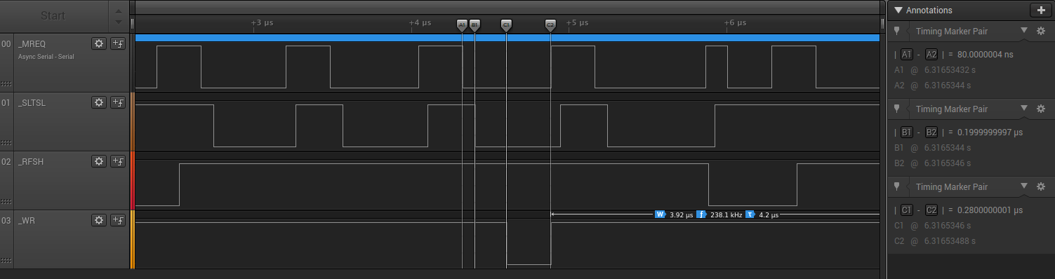
So in order to ‘cheat a bit’, the idea is read the databus midway through the _WR low and then exit the interrupt service routine, and hence ‘give some time back’ to the main loop. It only exits the interrupt service routine ‘a little early’ compared to a read. Obviously a read needs to wait until _MREQ goes high (which is also roughly when _WR goes high). So the math for a write is that it will take us about 100ns or a little more to go from _MREQ low to the start of the interrupt service routine. So _SLTSL should be low by then, but the code checks this anyway, and as mentioned before, that also gives the code an ‘early exit’ if _SLTSL is not low. There is a fair bit of logic that happens to ‘decide’ what to do next … but I had added some enforced extra delays, and at least for some of the writes, i was sampling the databus roughly midway through the _WR low period, but as I said, I was a little inconsistent, so some writes would have had the databus being sampled towards the start of the _WR low period. That must have been fine on the Omega, but not fine on the FS-A1.
So that seems to be mostly working now. Hopefully it helps out when using it on other MSX machines too.
I guess this all highlights the difficulty for creating a ROM/FDC emulator for a group of machines (eg. MSX and MSX2 machines) vs a single machine (eg. the TI 99/4a). There’s enough variations within a standard like MSX to ‘make it challenging’.
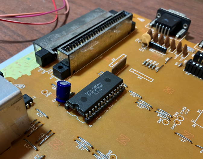
The main other thing I’ve done on the FS-A1 is to desolder the ROM and replace it with a socket so I can use a flash ROM. There’s a good thread on msx.org about replacing the FS-A1 ROM . The photo below show’s the original ROM , but with a socket I put in. Desoldering is always an adventure. More recently I’ve quite liked using that ‘alloy that mixes with solder to change the melting point’ stuff such as Chip Quik or Fast Chip to do desoldering. You don’t need as much heat, and this is a single sided board, so the ROM chip virtually fell out in under a minute. The downside of these alloy things (at least for me) is I tend to make a mess and have blobs everywhere , and probably spent an hour trying to clean up my mess. I ended up using a 27SF512 I had handy (so the 32K BASIC immediately followed by the sub rom, leaving 16K empty at the end). That work’s great and just boots me straight to BASIC. No more F8!
On another note, I have recently started going back to the code of many of these ROM/FDC emulators and feeding back some updates from some of the one’s I’ve done more recently.
- The TI 99/4a ended up with multiple drive support, so I am trying to go back and add that to some of the other ones, as all of them (except the TI) had only supported a single drive. As of now, the spectravideo-floppy-emulator and msx-rom-and-floppy-emulator also have two drive support.
- The dragon-rom-and-floppy-emulator is meant to support the Dragon 32 and Tandy Coco (1 and 2), but there are enough subtle differences that I have tended to use a different branch for the Tandy, compared to the Dragon. However, I think I finally have that sorted now too to be able to have one branch that supports both.